Connecting
4.3 Control/status interface - X8
SINAMICS V90, SIMOTICS S-1FL6
Operating Instructions, 04/2019, A5E36037884-007
119
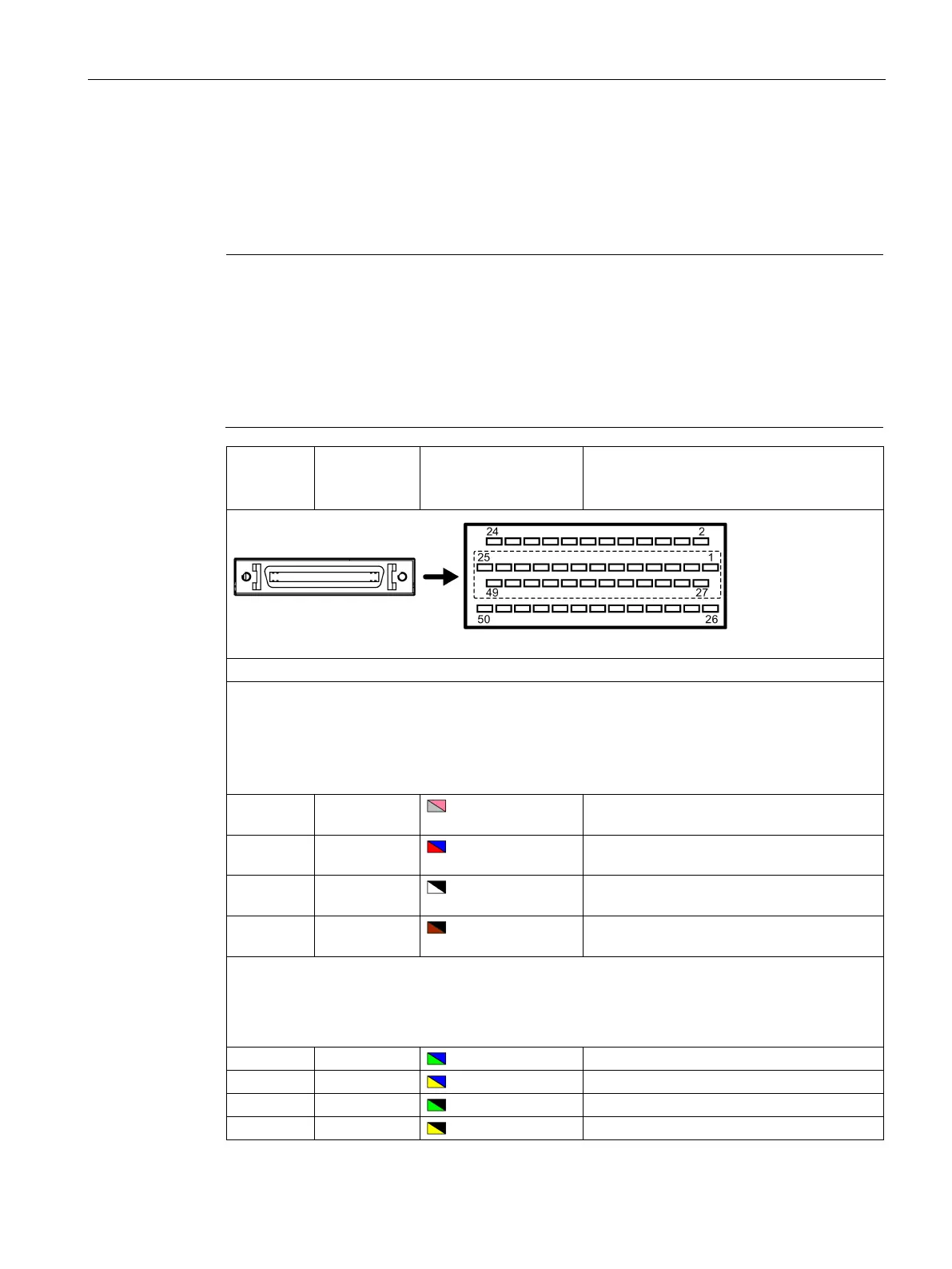
Control/status interface - X8
The pins with an asterisk (*) have been redefined in the table below, wherein DO4 (+/-) to
DO6 (+/-) are used for the servo drive to support the wiring of
the NPN and the PNP
types.
Note
The pin definition updates are applicable only when the FS (function state) version is as
follow
s:
V90 200 V: FS02 and the later
V90 400 V: FS04 and the later
Refer to the rating plate on the drive housing for the FS version of a SINAMICS V90 servo
drive.
Wire color on the set-
point cable exposed
side
Pulse train inputs (PTI)/Pulse train encoder outputs (PTO)
1, 2, 26, 27:
Position setpoint with pulse train input
High-speed 5 V differential pulse train input (RS485)
Maximum frequency: 1MHz
Signal transmission of this channel has better noise immunity
1 PTIA_D+ Gray-Pink High-speed 5 V differential pulse train input A
2 PTIA_D- Red-Bule High-speed 5 V differential pulse train input A
26 PTIB_D+ White-Black High-speed 5 V differential pulse train input B
27 PTIB_D- Brown-Black High-speed 5 V differential pulse train input B
36, 37, 38, 39:
Position setpoint with pulse train input
24 V single end pulse train input
Maximum frequency: 200 kHz
24 V pulse train input A, positive
24 V pulse train input A, ground
24 V pulse train input B, positive
24 V pulse train input B, ground

 Loading...


