Appendix
A.2 Motor selection
SINAMICS V90, SIMOTICS S-1FL6
Operating Instructions, 04/2019, A5E36037884-007
425
This section uses a ball screw mechanism as an example to illustrate the motor selection
procedure.
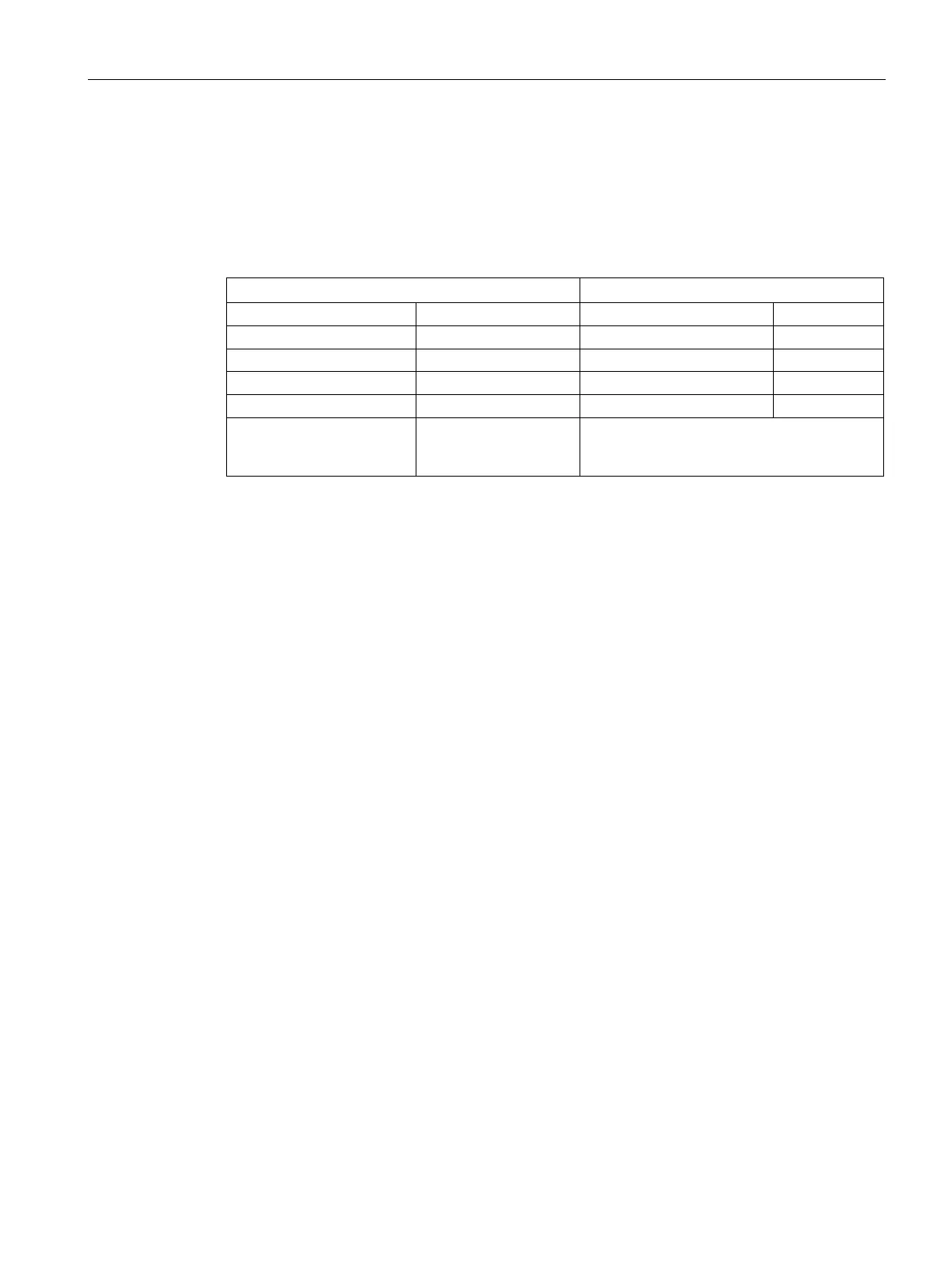
The following table lists the data related to the ball screw mechanism and operation pattern.
Ball screw length (B
l
) 2 m Constant motion time (t
u
) 0.7 s
d
d
Ball screw pitch (B
p
) 0.04 m Cycle time (t
c
) 2 s
ŋ
Coupler inertia (J
c
) 20 x 10
-6
kg·m
2
(refer to
the supplier's product
-
1.
B
w
= ρ x π x (Bd/2)
2
x B
l
= 19.85 kg
2.
J
l
= J
c
+ J
b
= J
c
+ 1/8 x B
w
x B
d
2
+ W x B
p
2
/ 4π
2
= 5.61 x 10
-3
kg·m
2
3.
If a 1000 W motor is selected, J
m
(motor inertia) = 1.57 x 10
-3
kg·m
2
Therefore, J
l
/ J
m
(inertia ratio) = 3.57 < 5 times
4.
V
max
(maximum travelling speed) = 2L / (t
a
+ 2t
u
+ t
d
) = 5.89 m/s
N
max
(maximum rotational speed) = 60 x V
max
/ B
p
= 882 rpm < 2000 rpm (rated speed)
5.
T
m
(moving torque) = (μgW + F) x B
p
/ 2πB
η
= 0.069 Nm
T
a
(acceleration torque) = [(J
l
+ J
m
) x 2 πN / T
a
] + T
m
= 4.49 Nm
T
d
(deceleration torque) = [(J
l
+ J
m
) x 2 πN / T
d
] - T
m
= 4.35 Nm
Therefore, T
rms
(effective torque) =√(T
a
2
x t
a
+ T
m
2
x t
b
+ T
d
2
x t
d
) / t
c
= 1.71 Nm < 4.78 Nm
(rated torque)
6.
According to the above calculated speed, torque, and inertia ratio, you are recommended
to select 1000 W motors, i.e. 1FL6062.

 Loading...


