Control functions
7.8 Communicating with the PLC
SINAMICS V90, SIMOTICS S-1FL6
Operating Instructions, 04/2019, A5E36037884-007
281
DI simulation example in S control mode
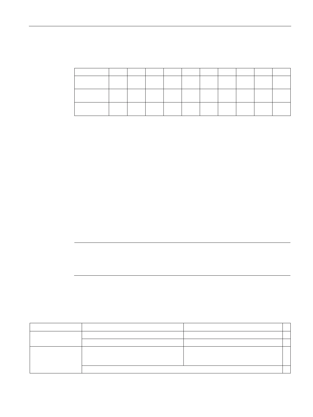
In S control mode, the default digital input signal assignment is as follows:
Signal SON REST CWL CCWL CWE CCWE SPD1 SPD2 EMGS C-
Register
Bit 0 Bit 1 Bit 2 Bit 3 Bit 4 Bit 5 Bit 6 Bit 7 Bit 8 Bit 9
Register
Bit 0 Bit 1 Bit 2 Bit 3 Bit 4 Bit 5 Bit 6 Bit 7 Bit 8 Bit 9
For more information about the DI assignment, refer to "Digital inputs/outputs (DIs/DOs)
(Page 122)".
● Set the simulation mode for DI1
To simulate DI1 with Modbus, you need to set bit 0 = 1 for register 40281.
● Set the setpoint for DI1
After the simulation mode of DI1 is set, you can set the setpoint for DI1 with register
40283 to enable the DI signal.
In S control mode, DI1 is assigned with SON by default, so we need to trigger a rising
edge to enable the SON signal. Set bit 0 = 0 for register 40283 and then set the bit to 1. A
rising edge is triggered. The motor is now in "S ON" state.
The SINAMICS V90 servo drive supports acyclic communication via data set 47.
The maximum data length per request is 240 bytes.
Note
Values in italics
Values in italics in the following tables mean that you have to adjust these values for a
Data block setting
Reading parameter values
The table below formats a request to read parameters.
Reference
00 hex ... FF hex
02 hex (ID of drive objects, at V90 always = 2)
10 hex:
Parameter value
00 hex ... EA hex
(For parameters without index: 00 hex)
4
Parameter number
0001 hex ... FFFF hex

 Loading...


