Explanations for the function diagrams
Function diagrams
2-503
© Siemens AG 2011 All Rights Reserved
SINAMICS G120 Control Units CU230P-2 Parameter Manual (LH9), 01/2011
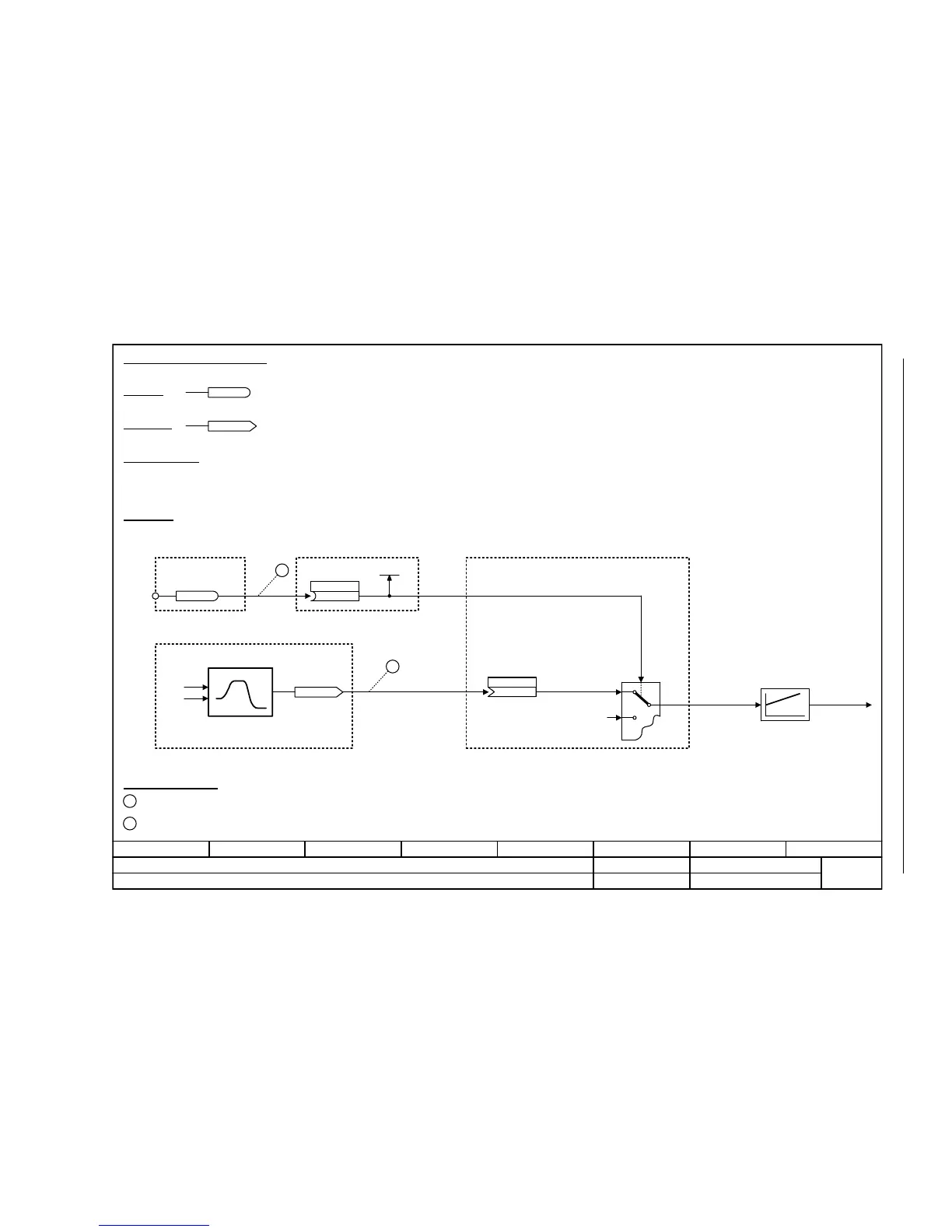
Fig. 2-4 1030 – Handling BICO technology
- 1030 -
Function diagram
87654321
FP_1030_97_61.vsd
Explanations for the function diagrams
G120 CU230P-2
13.12.2010 V4.4
Handling BICO technology
r0723.15
r0723
r0722.0
1
2
722.0
p1055[C]
Kl.5
r0967.8
[2220] [2501]
[3020]
r1050
[3030]
2
1 p1055[0] = 722.0
p1070[0] = 1050
Main setpoint
(755[0])
p1070.[C]
Handling BICO technology
Binector:
Connector:
Raise
Connectors are "analog signals" that can be freely interconnected (e.g. percentage variables, speeds or torques).
Connectors are also "CO:" display parameters (CO = Connector Output).
Parameterization:
At the signal destination, the required binector or connector is selected using appropriate parameters:
"BI:" parameter for binectors (BI = Binector Input)
or
"CI:" parameter for connectors (CI = Connector Input)
Example:
The main setpoint for the speed controller (CI: p1070) should be received from the output of the motorized potentiometer
(CO: r1050) and the "jog" command (BI: p1055) from Digital Input DI0 (BO: r0722.0, Terminal 5 (Kl.5)) on the CU230.
Control bit 8
Digital input
DI0
Setpoint
channel
Motorized potentiometer
Jog setpoint 1
Speed controller
Parameterizing steps:
Terminal 5 (Kl.5) acts as "Jog bit 0".
The output of the motorized potentiometer acts as main setpoint for the speed controller.
Lower

 Loading...


