Faults and warnings
Function diagrams
2-649
© Siemens AG 2011 All Rights Reserved
SINAMICS G120 Control Units CU230P-2 Parameter Manual (LH9), 01/2011
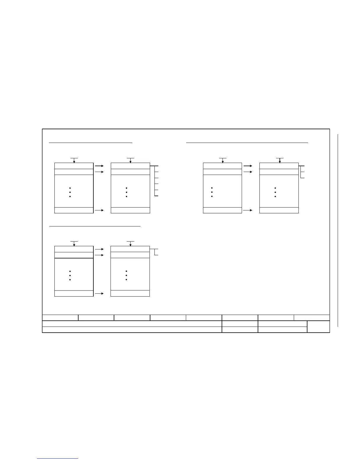
Fig. 2-135 8075 – Fault/warning configuration
- 8075 -
Function diagram
87654321
FP_8075_97_51.vsd
Faults and warnings
G120 CU230P-2
13.12.2010 V4.4
Fault/warning configuration
[0]
[1]
[19]
[0]
[1]
[19]
[0]
[1]
[19]
[0]
[1]
[19]
<1>
[0]
[1]
[19]
[0]
[1]
[19]
Changing the fault response for maximum 20 faults <1> Changing the message type - fault <==> alarm for maximum 20 faults/alarms <1>
Changing the acknowledge mode for maximum 20 faults <1>
0. Fault code
1. Fault code
19. Fault code
Fault response
Fault response
Fault response
0. Fault code
1. Fault code
19. Fault code
0 = NONE
1 = OFF1
2 = OFF2
3 = OFF3
5 = STOP2
6 = IASC/
DCBRK
0. Fault/alarm code
1. Fault/alarm code
19. Fault/alarm code
Fault/alarm type
Fault/alarm type
Fault/alarm type
1 = Fault
2 = Alarm
3 = No message
Acknowledge mode
Acknowledge mode
Acknowledge mode
1 = Acknowledgment is only possible using POWER ON
2 = Acknowledgment IMMEDIATELY after the cause has been removed.
The fault response, acknowledge mode and message type for all faults and alarms are set to meaningful default values in the factory setting.
Changes that may be required are only possible in specific value ranges specified by SIEMENS.
When the message type is changed, the supplementary information is tranferred from fault value r0949 to alarm value r2124 and vice versa.
F_no F response
0 ... 65535
p2100 (0)
Fault response
0 ... 6
p2101 (0)
Msg_no Msg_type
0 ... 65535
p2118 (0)
Message type
1 ... 3
p2119 (1)
Fault_no ackn_mode
0 ... 65535
p2126 (0)
Acknowledge mode
1 ... 2
p2127 (1)

 Loading...


