EasyManuals Logo

Siemens SINAMICS G120 User Manual

Siemens SINAMICS G120
732 pages
To Next Page IconTo Next Page
To Previous Page IconTo Previous Page
Page #598 background imageLoading...
Page #598 background image
Function diagrams
Vector control
2-598
© Siemens AG 2011 All Rights Reserved
SINAMICS G120 Control Units CU230P-2 Parameter Manual (LH9), 01/2011
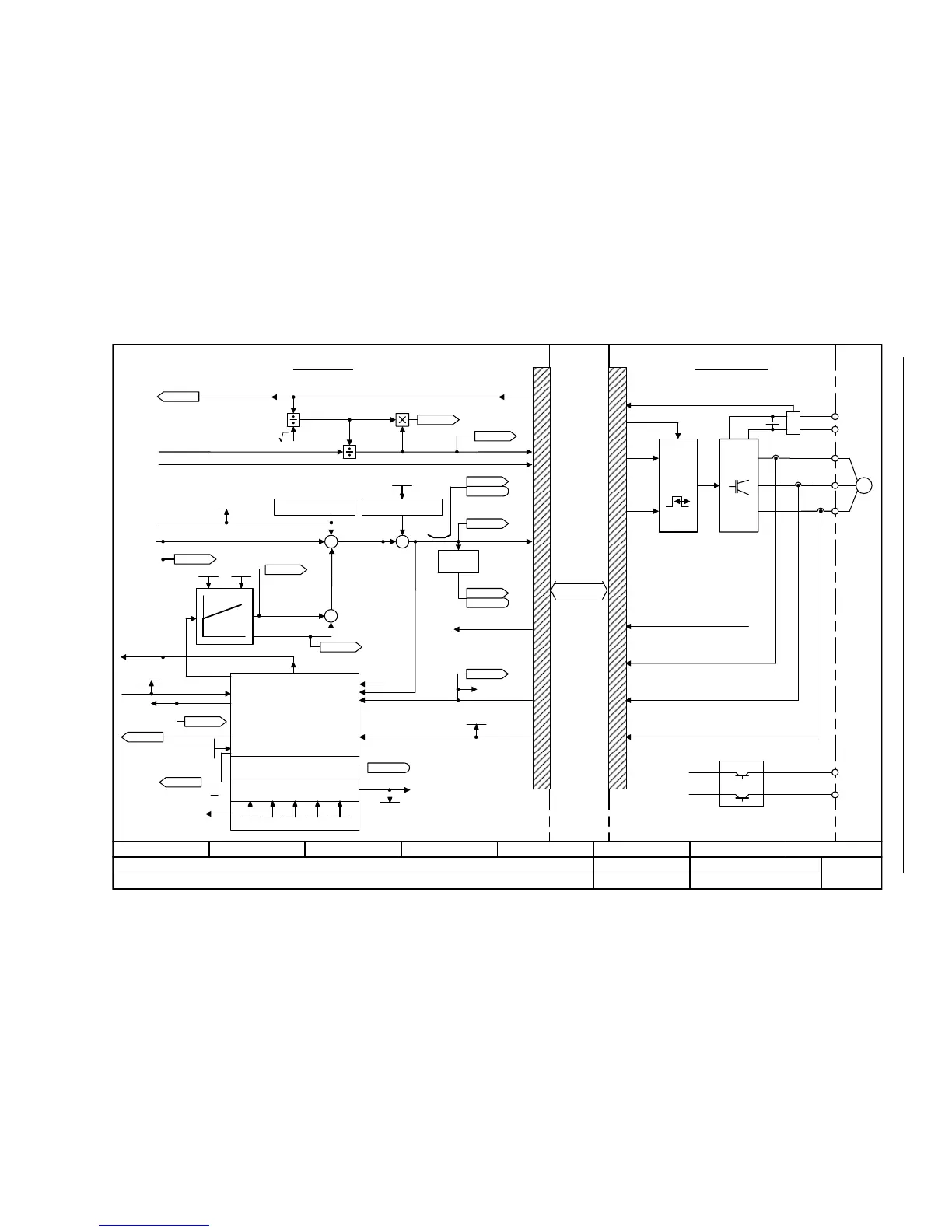
Fig. 2-89 6730 – Interface to the Power Module (ASM, p0300 = 1)
- 6730 -
Function diagram
87654321
FP_6730_97_54.vsd
Vector control
G120 CU230P-2
13.12.2010 V4.4
Interface to the Power Module (ASM, p0300 = 1)
[6723.1]
[6799.1]
PWM
M
~
+
U
V
W
+ BRP
-BRN
P24
M
p1750 p1755 p1756 p1758
Kp Tn
p1764
2
p1759
[1690.1]
[6640.1]
Iq
M
[6722.7]
r1408.12
[6714.1]
[6310.5]
[6640.5]
[6710.2]
[6714.1]
+
+
+
+
+
+
+
[8012.3]
[1690.8]
[6714.8]
[6799.1]
[6799.1]
[6799.1]
[2526.2]
Precontrol speed
n_act
Adaptation controller
Motor model (observer)
Stall monitoring
Model control
Vibration damping
Sign
+ or -
I_max Power Module
Brake control
I_max Power Module
Pulse enable HW
DC link voltage
Power Module
Control Unit
U_set
U_angle
r0070
Vdc act val [V]
r0072
U_output [Veff]
r0074
Modulat_depth [%]
f_Slip
r0065
Gain res_damp
p1740
ZSW cl-loop ctrl
r0056
r0056
.11
r0066
f_outp [Hz]
ZSW cl-loop ctrl
r0056
r0056
.07
R_stator act
r0395
r0087
Cos phi act
r0084
Flux act val [%]
r0094
Transformat_angle [°]
MotMod status
r1751
PM-IF
[6030.8]
[6310.1] [6799.1]
Current model
Outp_ph_seq rev
p1820
p1767
U_phase act val [V]
r0089[0..2]
r0069[0..6]
I_phase act value [A]
r0063[0..2]
n_act [1/min]
r1762, r1763, r1778
p1745
p1750 ... p1759
r1771
MotMod n_adapt Tn
[1/min]
r1770
MotMod n_adapt Kp
[1/min]

Table of Contents

Other manuals for Siemens SINAMICS G120

Questions and Answers:

Question and Answer IconNeed help?

Do you have a question about the Siemens SINAMICS G120 and is the answer not in the manual?

Siemens SINAMICS G120 Specifications

General IconGeneral
Power Range0.37 kW to 250 kW
Output Voltage0 V to Input Voltage
Frequency Range0 Hz to 650 Hz
Enclosure RatingIP20, IP21, IP55
Control ModesV/f control, vector control, servo control
Protection FeaturesOvervoltage, undervoltage, short circuit
Communication InterfacesPROFIBUS, PROFINET, Modbus RTU
Operating Temperature-10°C to +50°C
Cooling MethodAir cooling
Input Voltage200 V to 240 V, 380 V to 480 V, 500 V to 690 V

Related product manuals