Internal control/status words
Function diagrams
2-559
© Siemens AG 2011 All Rights Reserved
SINAMICS G120 Control Units CU230P-2 Parameter Manual (LH9), 01/2011
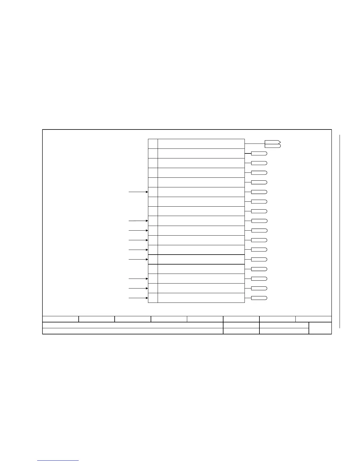
Fig. 2-53 2526 – Status word, closed-loop control
- 2526 -
Function diagram
87654321
FP_2526_97_61.vsd
Internal control/status words
G120 CU230P-2
13.12.2010 V4.4
Status word, closed-loop control
1
2
4
0
7
8
9
11
14
15
[6722.6]
[6722.3]
[6714.8]
[6220.8][6320.8]
[6220.8][6320.8]
3
5
6
12
13
10[6310.8]
<1>
<1>
<1>
<1>
<1>
[6060.7]
[6710.2]
[8012.5]
Only for V/f control
Status word closed-loop control (r0056)Bit No.
1 = Initialization completed
1 = De-magnetization completed
1 = Pulses enabled
1 = Soft starting available
1 = Magnetization completed
1 = Acceleration voltage active
1 = Frequency, negative
1 = Field weakening active
1 = Voltage limit active
1 = Slip limiting active
1 = Frequency limit active
1 = Current limiting controller, voltage output active
1 = Current/torque limiting active
1 = Vdc_max controller active
1 = Vdc_min controller active
ZSW cl-loop ctrl
r0056
r0056
1 = Starting boost active
r0056.0
r0056.1
r0056.4
r0056.5
r0056.11
r0056.12
r0056.2
r0056.6
r0056.9
r0056.13
r0056.14
r0056.15
r0056.3
r0056.7
r0056.8
r0056.10
<1>
Only for Power Modules PM230/PM240
Only for Power Modules PM240 and for PM230 with Vector Control
<2>
<3>
<2>
<3>
[6031.6] [6710.2]
[6730.5][6731.5][6732.4]
[6730.5][6731.5][6732.4]

 Loading...


