Technology functions
Function diagrams
2-623
© Siemens AG 2011 All Rights Reserved
SINAMICS G120 Control Units CU230P-2 Parameter Manual (LH9), 01/2011
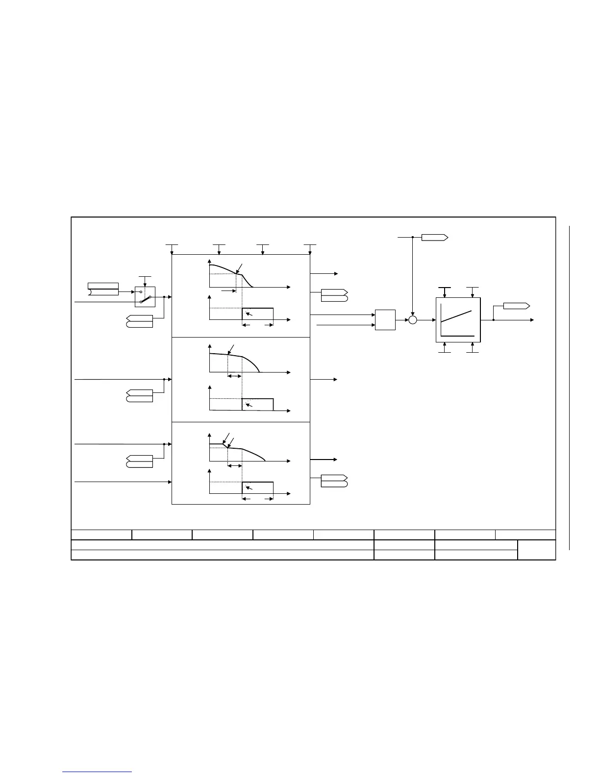
Fig. 2-112 7017 – DC brake (p0300 = 1)
- 7017 -
Function diagram
87654321
FP_7017_97_54.vsd
Technology functions
G120 CU230P-2
13.12.2010 V4.4
DC brake (p0300 = 1)
MIN
[6714]
Kp Tn
p0347
p1234
p1233
p1232
p0347
p1232
<1>
<2>
<3>
<1>
<2>
0
4
t
t
t
t
OFF
p1231 = 5 (OFF1/OFF3)
Pulse disable
Pulse disable
n_act
n_set
|I_set|
n_act
n_set
Braking response
|I_set|
|I_act|
The DC braking current is determined during automatic calculation (p0340 = 1).
The de-magnetization time is determined during automatic calculation (p0340 = 1, 3).
To pulse disable
To sequencer
From I²t control [8014]
|I_set|
Current actual values
The parameters of the
I_max current controller are also used.
To control [6730]
To V/f characteristic
[6300]
(0)
DCBRK Akt
p1230 [C]
DCBRK config
0 ... 14
p1231 [D] (0)
DCBRK I_brake
0.00 ... 10000.00 [Aeff]
p1232 [D] (0.00)
DCBRK time
0.0 ... 3600.0 [s]
p1233 [D] (1.0)
DCBRK n_start
0.00 ... 210000.00 [1/min]
p1234 [D] (210000.00)
DCBRK ZSW
r1239
r1239
.10
DCBRK ZSW
r1239
r1239
.8
I_max_U_ctrl Kp
0.000 ... 100000.000
p1345 [D] (0.000)
I_max_U_ctrl Tn
0.000 ... 50.000 [s]
p1346 [D] (0.030)
r0072
U_output [Veff]
DCBRK ZSW
r1239
r1239
r0068[0..1]
I_act abs val [Aeff]
I_ctrl Kp
0.000 ... 100000.000
p1715 [D] (0.000)
I_ctrl Tn
0.00 ... 1000.00 [ms]
p1717 [D] (2.00)
Mot t_de-excitat.
0.000 ... 20.000 [s]
p0347 [D] (0.000)
14
To pulse disable
To sequencer
To pulse disable
To sequencer
|I_act|
p1234
p1233
p1232
p0347
t
t
Pulse disable
n_act
n_set
|I_set|
|I_act|
DC brake fault response
p1231 = 4 (control command)
DCBRK ZSW
r1239
r1239
DCBRK ZSW
r1239
r1239
DC braking when starting speed for DC braking (p1234) is fallen below.
<3>

 Loading...


