Function diagrams
Communication
2-524
© Siemens AG 2011 All Rights Reserved
SINAMICS G120 Control Units CU230P-2 Parameter Manual (LH9), 01/2011
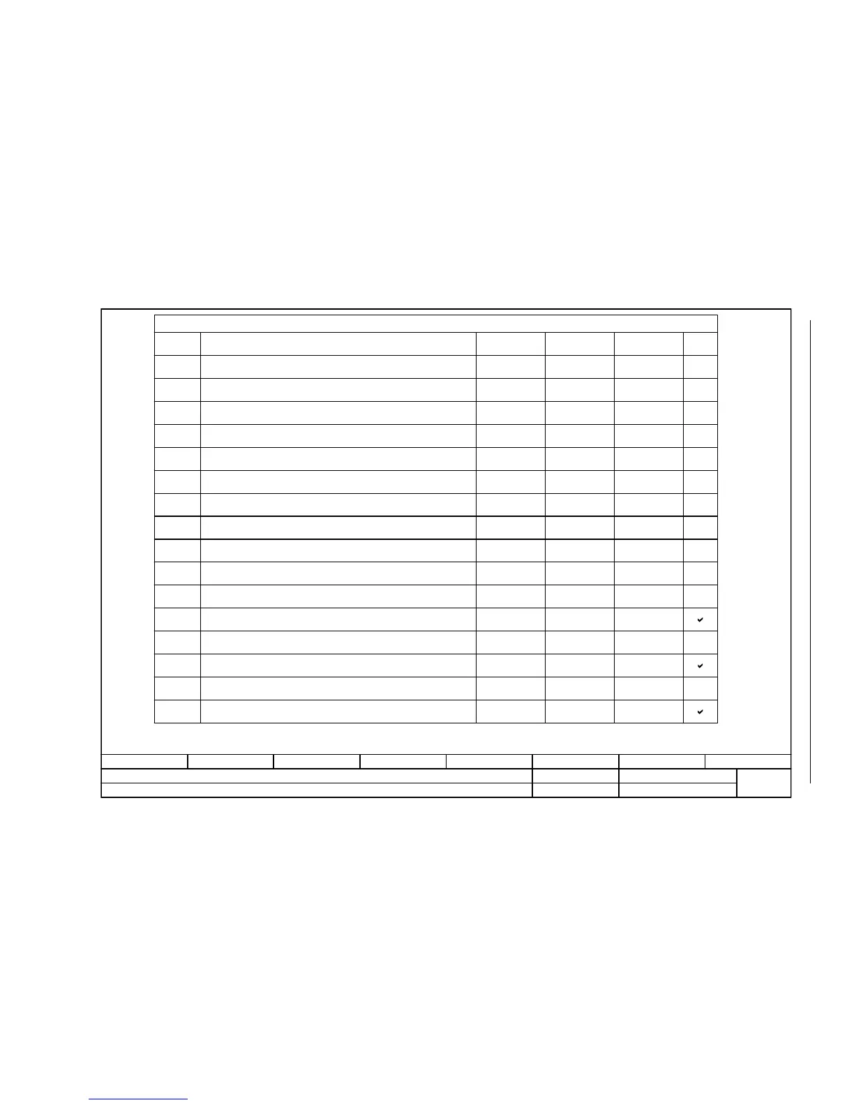
Fig. 2-21 9352 – ZSW1 status word interconnection
- 9352 -
Function diagram
87654321
FP_9352_97_62.vsd
Fieldbus Interface (USS, Modbus, BACnet on RS485)
G120 CU230P-2 HVAC
13.12.2010 V4.4
ZSW1 status word interconnection
<1>
ZSW1.0
ZSW1.1
ZSW1.2
ZSW1.3
ZSW1.4
ZSW1.5
ZSW1.6
ZSW1.8
ZSW1.9
ZSW1.11
ZSW1.12
ZSW1.13
ZSW1.14
ZSW1.15
ZSW1.7
ZSW1.10
<2>
p2080[2] = r0899.2
p2080[3] = r2139.3
p2080[4] = r0899.4
p2080[5] = r0899.5
p2080[6] = r0899.6
p2080[7] = r2139.7
p2080[8] = r2197.7
p2080[9] = r0899.9
p2080[10] = r2199.1
p2080[11] = r1407.7
p2080[13] = r2135.14
p2080[15] = r2135.15
p2080[0] = r0899.0
p2080[1] = r0899.1
p2080[14] = r2197.3
[2503.7]
[2548.7]
[2503.7]
[2503.7]
[2503.7]
[2548.7]
[2534.7]
[2503.7]
[2536.7]
[2522.7]
[2548.7]
[2548.7]
[2503.7]
[2503.7]
[2534.7]
[8060]
[8065]
[8011]
[2503]
[8010]
[6060]
[8016]
[8014]
[8011]
-
-
-
-
-
-
-
-
-
-
-
-
-
<1>
Signal sources for fieldbus ZSW1 (p0700 = 6)
Signal
Meaning
Interconnection
parameters
[Function diagram]
internal control word
[Function diagram]
signal target
Inverted
1 = Ready for switching on
1 = Ready for operation (DC link loaded, pulses inhibited)
1 = Operation enabled (drive follows n_set)
1 = Fault present
1 = No coast down active (OFF2 inactive)
1 = No fast stop active (OFF3 inactive)
1 = Switching on inhibited active
1 = Alarm present
1 = Speed setpoint - actual value deviation within tolerance t_off
1 = Control requested
1 = f or n comparison value reached/exceeded
1 = I, M, or P limit not reached
Reserved
1 = No motor overtemperature alarm
1 = Motor rotates forwards (n_act 0)
0 = Motor rotates backwards (n_act < 0)
1 = No alarm, thermal overload, power unit
The ZSW1 is generated using the binector-connector converter (BI: p2080[0...15], inversion: p2088[0].0...p2088[0].15)
The drive is ready to accept data.
Sequence control
Sequence control
Sequence control
Sequence control
Sequence control
Sequence control
<2>
-- -

 Loading...


