Signals and monitoring functions
Function diagrams
2-641
© Siemens AG 2011 All Rights Reserved
SINAMICS G120 Control Units CU230P-2 Parameter Manual (LH9), 01/2011
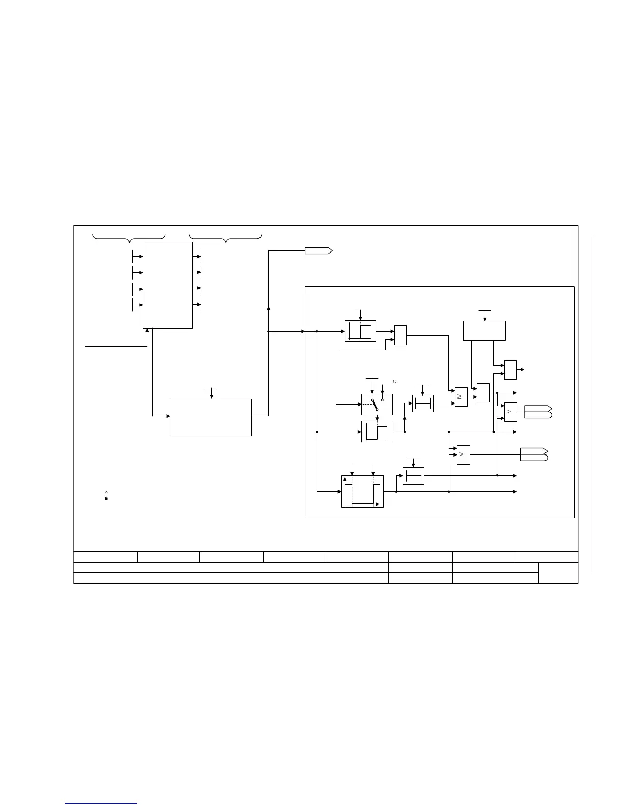
Fig. 2-128 8016 – Thermal monitoring, motor
- 8016 -
Function diagram
87654321
FP_8016_97_51.vsd
Signals and monitoring functions
G120 CU230P-2
13.12.2010 V4.4
Thermal monitoring, motor
<1>
<2>
<3>
<4>
1 =
2 =
T0
&
&
1
<1>
I_max-Reduktion
[1690.1][6640.2]
p0610 = 1
-140 °C 250 °C <2>
0
1
&
1
1
T0
KTY PTC
0
1
<3>
<5>
1650
4 =
Rated motor temperature rise Calculated motor temperatures
Thermal
3-mass-model
(for induction motors
only)
For KTY and PTC, the value p0606 = 0 has a different meaning:
KTY: 0 The output of the timer is always switched out (logical 0)
PTC: 0 Delay time = 0 s
Switch-on delay p0607 = 0 suppresses fault F07016.
For KTY and "No sensor", temperature as defined in the model.
The relevant rated response temperature in °C depends on the temperature sensor
chosen by the motor manufacturer.
0 = No sensor
PTC alarm and time
KTY84
Bimetal NC contact
alarm with time step
KTY sensor type
(threshold not applicable for PTC)
Sensor type
Fault
response
Suppress fault
p0610 = 0
F07011
"Motor overtemperature"
A07910
"Motor overtemperature"
A07016
"Motor temperature
sensor fault, fault"
A07015
"Motor temperature
sensor fault alarm"
r0035
Mot temp [°C]
ZSW fault/alarm 2
r2135
r2135
.12
ZSW fault/alarm 2
r2135
r2135
.14
Mot temp response
0 ... 2
p0610 [D] (1)
0 : No response, only warning, no reduction of I_max
1 : Warning and reduction of I_max and fault (F07011)
2 : Warning and fault, no reduction of I_max
p0610 =
<5>
<4>
T_mes
Mot_temp_sens type
0 ... 4
p0601 [D] (0)
Mot T_ambient
-40 ... 80 [°C]
p0625 [D] (20)
Mot_temp flt thr
0.0 ... 240.0 [°C]
p0605 [D] (145.0)
Mot_temp timer
0.000 ... 600.000 [s]
p0606 [D] (0.000)
Mot_temp al thr
0.0 ... 240.0 [°C]
p0604 [D] (130.0)
Sensor fault time
0.000 ... 600.000 [s]
p0607 [D] (0.100)
MotTMod T_amb. [°C]
r0630 [D]
MotTMod T_core [°C]
r0631 [D]
MotTMod T_copper [°C]
r0632 [D]
MotTMod T_rotor [°C]
r0633 [D]
Mot T_over core
20 ... 200 [K]
p0626 [D] (50)
Mot T_over stator
20 ... 200 [K]
p0627 [D] (80)
Mot T_over rotor
20 ... 200 [K]
p0628 [D] (100)

 Loading...


