Communication
Function diagrams
2-523
© Siemens AG 2011 All Rights Reserved
SINAMICS G120 Control Units CU230P-2 Parameter Manual (LH9), 01/2011
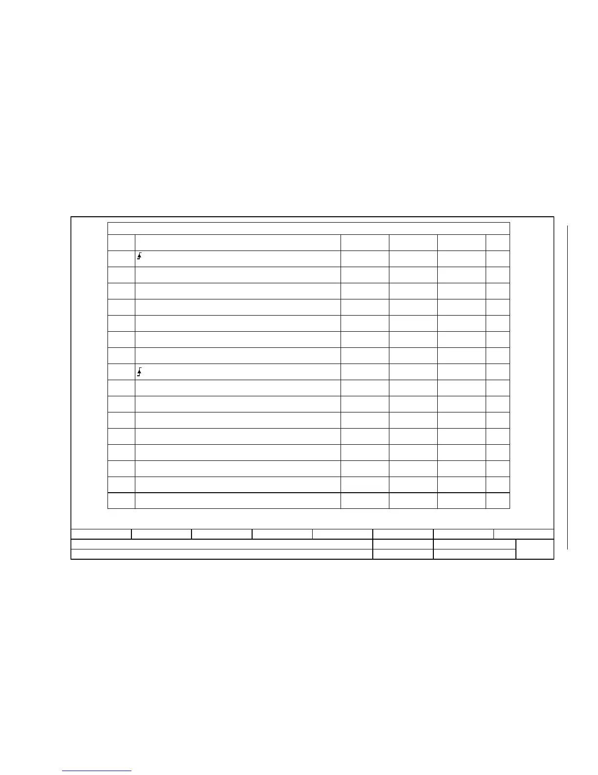
Fig. 2-20 9342 – STW1 control word interconnection
- 9342 -
Function diagram
87654321
FP_9342_97_62.vsd
Fieldbus Interface (USS, Modbus, BACnet on RS485)
G120 CU230P-2 HVAC
13.12.2010 V4.4
STW1 control word interconnection
STW1.0
STW1.1
STW1.2
STW1.3
STW1.4
STW1.5
STW1.6
STW1.8
STW1.9
STW1.11
STW1.12
STW1.13
STW1.14
STW1.15
STW1.7
STW1.10
p0848[0] = r2090.2
p0852[0] = r2090.3
p2103[0] = r2090.7
-
-
p0854[0] = r2090.10
p1113[0] = r2090.11
-
p1035[0] = r2090.13
p1036[0] = r2090.14
-
p0840[0] = r2090.0
p0844[0] = r2090.1
[2501.3]
[2501.3]
[2501.3]
[2501.3]
[2501.3]
[2546.1]
-
-
[2501.3]
[2505.3]
-
[2505.3]
[2505.3]
-
[2501.3]
[2501.3]
[8060]
-
-
[2501]
[3040]
-
[3020]
[3020]
-
-
-
-
-
-
-
-
-
-
-
-
-
-
-
-
-
<1>
<1>
Signal targets for fieldbus STW1 (p0700 = 6)
Signal
Meaning
Interconnection
parameters
[Function diagram]
internal control word
[Function diagram]
signal target
Inverted
0 = OFF1 (braking with ramp-function generator, then pulse cancellation & ready for switching on)
= ON (pulses can be enabled)
1 = No OFF2 (enable is possible)
0 = OFF2 (immediate pulse suppression and switching on inhibited)
1 = No OFF3 (enable is possible)
0 = OFF3 (braking with the OFF3 ramp p1135, then pulse suppression and switching on inhibited)
1 = Enable operation (pulses can be enabled)
0 = Inhibit operation (cancel pulses)
1 = Operating condition (the ramp-function generator can be enabled)
0 = Inhibit ramp-function generator (set the ramp-function generator output to zero)
1 = Enable the ramp-function generator
0 = Stop the ramp-function generator (freeze the ramp-function generator output)
1 = Enable setpoint
0 = Inhibit setpoint (set the ramp-function generator input to zero)
= Acknowledge faults
Reserved
Reserved
1 = Control via PLC
1 = Dir of rot reversal
Reserved
1 = Motorized potentiometer, setpoint, raise
1 = Motorized potentiometer, setpoint, lower
Reserved
Bit 10 in STW1 must be set to ensure that the drive accepts the process data.
Sequence control
Sequence control
Sequence control
Sequence control
[3060] [3070] [3080]
[3060] [3070]
[3060] [3070] [3080]
p1140[0] = r2090.4
p1141[0] = r2090.5
p1142[0] = r2090.6

 Loading...


