Overview
Function diagrams
2-507
© Siemens AG 2011 All Rights Reserved
SINAMICS G120 Control Units CU230P-2 Parameter Manual (LH9), 01/2011
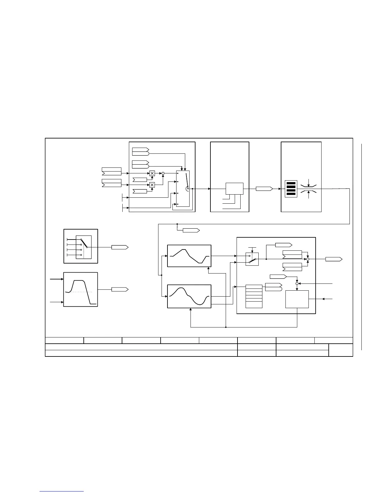
Fig. 2-7 1550 – Setpoint channel
- 1550 -
Function diagram
87654321
FP_1550_97_51.vsd
Overviews
G120 CU230P-2
13.12.2010 V4.4
Setpoint channel
+
+
+ / -
+
ZSW
p1076
p1071
pos
neg
(-1)
1
0
+
+
+
[1700.1]
0 0
0 1
1 0
1 1
Main setpoint
(755[0])
p1070 [C]
Suppl setpoint
(0)
p1075 [C]
r1024
n_set_fixed eff [1/min]
Jog 1 n_set
-210000.000 ... 210000.000 [1/min]
p1058 [D] (150.000)
Jog 2 n_set
-210000.000 ... 210000.000 [1/min]
p1059 [D] (-150.000)
raise
Main/supplementary setpoint, setpoint
scaling, jogging
r1050
Mop setp after RFG [1/min]
Motorized potentiometer
Fixed speed setpoints
Expanded ramp-function
generator
Basic ramp-function
generator
n_set_1
n_set_4
n_set_5
Simulate ramp-function generator
Ramp-function generator selection,
status word, tracking
Direction of rotating
limiting/changeover
Skip (suppression)
bandwidth and speed limiting
Ramp-function
generator
tracking
RFG setpoint
at the input
STW seq_ctrl
r0898
r0898
.8
STW seq_ctrl
r0898
r0898
.9
RFG selection
0 ... 1
p1115 (1)
r1150
RFG n_set at outp [1/min]
n_act
M_limit
n_ctrl n_set 1
(0)
p1155 [C]
RFG ZSW
r1199
r1199
n_ctrl n_set 2
(0)
p1160 [C]
r1438
n_ctrl n_set [1/min]
lower
r1119
RFG setp at inp [1/min]
[3010]
[3030] [3040] [3050]
[3070]
[3060]
[3080]
[3020]
r1114
Setp after limit
[1/min]
r1170
n_ctrl setp sum [1/
min]

 Loading...


