Input/Output Terminals
Function diagrams
2-517
© Siemens AG 2011 All Rights Reserved
SINAMICS G120 Control Units CU230P-2 Parameter Manual (LH9), 01/2011
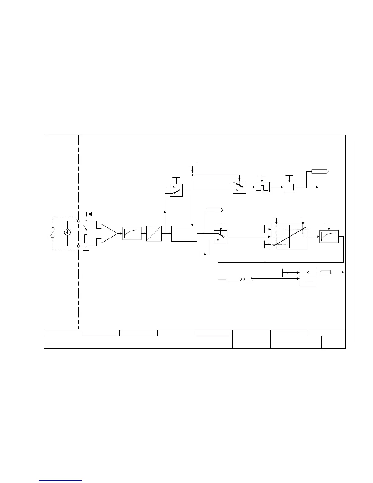
Fig. 2-16 9568 – Analog input 2 (AI2)
- 9568 -
Function diagram
87654321
FP_9568_97_01.vsd
External Interfaces
G120 CU230P-2
13.12.2010 V4.4
Analog input 2 (AI2)
3
3
20 mA
T0
<2>
0 20 mA
°C
Kl.50
[%]
xy
<2> <2>
A
D
+
-
<1>
<1>
x
1
y
2
x
2
y
1
y
x
[%]
y
x
2
x
1
<2> <3>
% 100
xx
21
•
<3>
AI2 TEMP I
1
0
20 mA
1
0
Current
Hardware smoothing
100 μs
Scaling
Caution:
The voltage between an input (Kl.50) and the ground point (Kl.51) must not exceed 35 V.
When the load resistor is switched in (DIP switch in position I), the voltage between the input terminals
must not exceed 10 V or the impressed current 80 mA.
For p0756 = 2, 3 the units are mA.
For p0756 = 6, 7 the units are °C.
Possible settings p0756[2]:
= 2: 0 mA ... +20 mA (Default for AI2)
= 3: 4 mA ... +20 mA with monitoring
= 6: Ni1000
= 7: PT1000
= 8: No sensor
F03505
"Wire
breakage"
CU wire brk t_del
0 ... 1000 [ms]
p0762 (100)
CU AI sim_mode
0 ... 1
p0797 (0)
CU AI type
0 ... 8
p0756 (4)
CU WireBrkThresh
0.00 ... 20.00
p0761 (2.00)
CU AI T_smooth
0.0 ... 1000.0 [ms]
p0753 (0.0)
CU AI sim setp
-50.000 ... 2000.000
p0798 (0.000)
CU AI char y1
-1000.00 ... 1000.00 [%]
p0758 (0.00)
CU AI char y2
-1000.00 ... 1000.00 [%]
p0760 (100.00)
CU AI char x1
-50.000 ... 160.000
p0757 (0.000)
CU AI char x2
-50.000 ... 160.000
p0759 (10.000)
CU AI sim_mode
0 ... 1
p0797 (0)
Kl.51
Kl. = Terminal
Sampling time of the AI : 4 ms
r0755
CU AI value in % [%]
[2]
Ni1000
PT1000
°C
Ni1000/PT1000
<4>
Wire breakage sensing only activated when p0756 = 3.
<2>
<4>
<2>
Type switching
Analog input
I
GND
[2] (0)
[2] (2)
[2] (0.00)
[2] (100)
[2] (0)
[2] (0.00)
[2] (0.00)
[2] (0.00)
[2] (0.00) [2] (0.00)
[2] (0.00)
CU AI status word
r0751
r0752
CU AI U/I_inp act
[2]
Reference
quantities
p2000 r2004

 Loading...


