Communication
Function diagrams
2-547
© Siemens AG 2011 All Rights Reserved
SINAMICS G120 Control Units CU230P-2 Parameter Manual (LH9), 01/2011
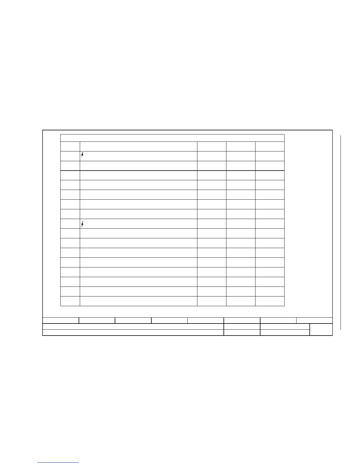
Fig. 2-42 9220 – Control word, CANopen
- 9220 -
Function diagram
87654321
FP_9220_97_68.vsd
CANopen
G120 CU230P-2 CAN
13.12.2010 V4.4
Control word, CANopen
STW1.0
STW1.1
STW1.2
STW1.3
STW1.4
STW1.5
STW1.6
STW1.8
STW1.9
STW1.11
STW1.12
STW1.13
STW1.14
STW1.15
STW1.7
STW1.10
p0848[0] = r2090.2
p0852[0] = r2090.3
-
-
-
p2103[0] = r2090.7
-
-
-
pxxxx[y] = r2090.11
pxxxx[y] = r2090.12
pxxxx[y] = r2090.13
pxxxx[y] = r2090.14
pxxxx[y] = r2090.15
p0840[0] = r2090.0
p0844[0] = r2090.1
[2501.3]
[2501.3]
-
-
-
[2546.1]
-
-
-
-
-
-
-
-
[2501.3]
[2501.3]
-
-
-
-
-
[8060]
-
-
-
-
-
-
-
-
-
<1>
<1>
-
Signal targets for control word CANopen (r8795)
Signal
= ON (pulses can be enabled)
Interconnection
parameters
[Function diagram]
internal control word
[Function diagram]
signal target
0 = OFF1 (braking with RFG, then pulse suppression and ready for switching on)
1 = No coast-down activated (enable possible)
0 = Activate coast-down (immediate pulse suppression and switching on inhibited)
1 = No fast stop activated (enable possible)
0 = Activate fast stop (OFF3 ramp p1135, then pulse suppression and switching on inhibited)
1 = Enable operation (pulses can be enabled)
0 = Inhibit operation (cancel pulses)
Reserved
Reserved
Reserved
= Acknowledge fault
Reserved
Reserved
Reserved
Can be freely connected
Can be freely connected
Can be freely connected
Can be freely connected
Can be freely connected
Depending on the position of the CANopen control word in p8750, the number of the binector to be connected changes.
Meaning

 Loading...


