Function diagrams
Internal control/status words
2-564
© Siemens AG 2011 All Rights Reserved
SINAMICS G120 Control Units CU230P-2 Parameter Manual (LH9), 01/2011
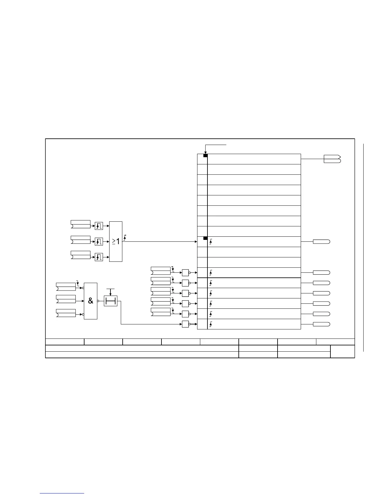
Fig. 2-58 2546 – Control word, faults/alarms
- 2546 -
Function diagram
87654321
FP_2546_97_51.vsd
Internal control/status words
G120 CU230P-2
13.12.2010 V4.4
Control word, faults/alarms
11
12
13
14
15
PROFIdrive-Bit
9
10
8
7
6
5
4
3
2
1
0
r2138.11
r2138.13
r2138.14
r2138.15
r2138.12
r2138.10
r2138.7
T0
<1>
<1>
<1>
<1>
<1>
<1>
<1>
<1>
<1>
<1>
<1>
<1>
Pulse generator
These parameters refer to the Command Data Sets (CDS)..
Control word, faults/alarmsBit No.
Reserved
Reserved
Reserved
Reserved
Reserved
Reserved
Reserved
Reserved
Reserved
= External alarm 1 (A07850)
= Acknowledge faults
= External alarm 2 (A07851)
= External alarm 3 (A07852)
= External fault 1 (F07860)
= External fault 2 (F07861)
= External fault 3 (F07862)
To alarm buffer [8065.1]
To alarm buffer [8065.1]
To alarm buffer [8065.1]
To fault buffer [8060.1]
To fault buffer [8060.1]
To fault buffer [8060.1]
To fault buffer [8060.1]
STW fault/alarm
r2138
r2138
(722.2)
1. Acknowledge
p2103 [C]
(0)
p2104 [C]
(0)
3. Acknowledge
p2105 [C]
Ext fault 3 t_on
0 ... 1000 [ms]
p3110 (0)
(1)
Ext fault 3 enab
p3111 [C]
(0)
Ext flt 3 enab neg
p3112 [C]
(1)
External fault 3
p2108 [C]
(1)
External alarm 1
p2112 [C]
(1)
External alarm 2
p2116 [C]
(1)
External alarm 3
p2117 [C]
(1)
External fault 1
p2106 [C]
(1)
External fault 2
p2107 [C]
1
1
1
1
1
1

 Loading...


