Overview
Function diagrams
2-511
© Siemens AG 2011 All Rights Reserved
SINAMICS G120 Control Units CU230P-2 Parameter Manual (LH9), 01/2011
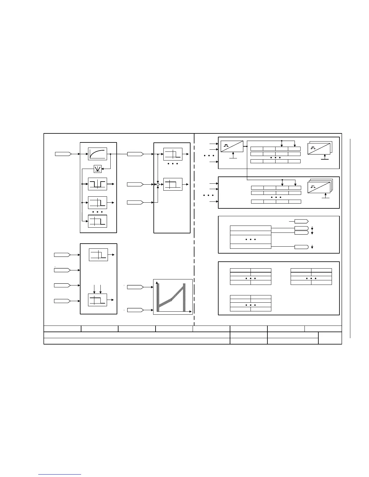
Fig. 2-11 1750 – Monitoring functions, faults, alarms
- 1750 -
Function diagram
87654321
FP_1750_97_51.vsd
Overviews
G120 CU230P-2
13.12.2010 V4.4
Monitoring functions, faults, alarms
r2109r0948r0949r0945
III
III
III
r2125r2123r2124r2122
III
III
Fxxxxx
Fyyyyy
Axxxxx
Ayyyyy
[0]
[15]
p2128
r2929
p2100[0]
[19]
[1]
p2101
p2126[0]
[19]
[1]
p2127
p2118[0]
[19]
[1]
p2119
[3080]
[6010]
[6640]
[6640]
[8010]
[6060]
[6714]
[8010]
n_max
[8010] Speed messages 1
[8013] load monitoring[8012] Torque messages
Motor locked
Limit value monitor
Fzzzzz
faults
Azzzzz
alarms
[8060] Fault buffer
[8065] Alarm buffer
Code Value
coming going
Code Value
coming going
[8070] Fault/alarm trigger word
Changes the fault response
Changes the message type
Changing the acknowledge mode
[8075] Fault/alarm configuration
r2169
n_act smth message [1/min]
r2169
n_act smth message [1/min]
r1539
M_max lower eff [Nm]
r1538
M_max upper eff [Nm]
r0079
M_set [Nm]
t_System relative
0 ... 4294967295 [ms]
p0969 (0)
Fault cases qty
0 ... 65535
p0952 (0)
Alarm counter
0 ... 65535
p2111 (0)
r0080
M_act [Nm]
[0]
r0063
n_act [1/min]
[0]
[8012]
[8011] Speed messages 2
r2169
n_act smth message [1/min]
[0]
[6031]
r1438
n_ctrl n_set [1/min]
r1170
n_ctrl setp sum
[1/min]

 Loading...


