Function diagrams
Signals and monitoring functions
2-638
© Siemens AG 2011 All Rights Reserved
SINAMICS G120 Control Units CU230P-2 Parameter Manual (LH9), 01/2011
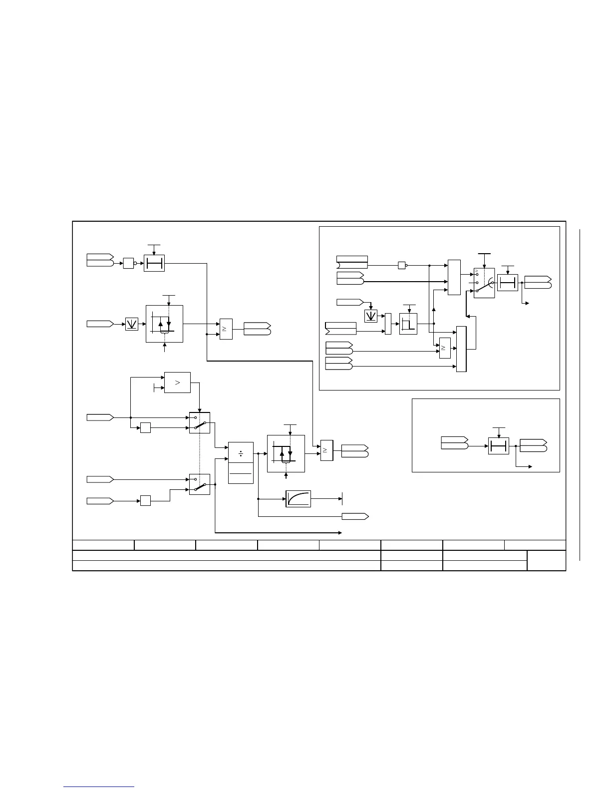
Fig. 2-125 8012 – Torque signals, motor locked/stalled
- 8012 -
Function diagram
87654321
FP_8012_97_54.vsd
Signals and monitoring functions
G120 CU230P-2
13.12.2010 V4.4
Torque signals, motor locked/stalled
0
1
0
1
1
0T
[6640.8]
[6640.8]
0
1
x
1
x
2
y
[%]
[Nm]
0
1
[2537.7]
1
1
2
1
x
% 100x •
2 % von p2194
2 % von p2174
[Nm]
[3080.1]
[2537.3]
[2536.3]
100 ms
[6060.8]
T0
F07902
[2536.3]
[6730.3]
T0
[8010.2]
F07900
[2522.7]
[2536.3]
[6060.8]
x
1
x
2
y
&
&
[2526.6]
Ramp-function generator operating
x1 > x2 = y = 1
(positive torque requested)
Requested
torque
Actual torque limit
Motor locked detection or motor locked monitoring
function (not for closed-loop torque control)
n_act smooth
signal < p2175
Stall detection or stall monitoring (not for V/f control)
ZSW monitor 3
r2199
r2199
.5
M_util t_off
0.0 ... 1000.0 [ms]
p2195 [D] (800.0)
r0079
M_set [Nm]
M_thresh val 1
0.00 ... 20000000.00 [Nm]
p2174 [D] (5.13)
ZSW monitor 2
r2198
r2198
.10
r0079
M_set [Nm]
r1538
M_max upper eff [Nm]
r1539
M_max lower eff [Nm]
M_thresh val 2
0.00 ... 100.00 [%]
p2194 [D] (90.00)
ZSW monitor 3
r2199
r2199
.11
M_util smooth [%]
r0033
r0081
M_Utilization [%]
(0)
Mot stall enab neg
p2144 [C]
ZSW n_ctrl
r1407
r1407
.7
Mot lock n_thresh
0.00 ... 210000.00 [1/min]
p2175 [D] (120.00)
r2169
n_act smth message [1/min]
ZSW cl-loop ctrl
r0056
r0056
.13
p1300
Mot lock t_del
p2177
ZSW monitor 2
r2198
r2198
.6
ZSW I_ctrl
r1408
r1408
.12
ZSW monitor 2
r2198
r2198
.7
Mot stall t_del
p2178
MIN
Load monit n_act
(0)
p3230 [C]
ZSW cl-loop ctrl
r0056
r0056
.12
1
<1>
<1>
Only evaluated with p2193 = 2 and V/f control.
0..4,7
20
5,6,
19
0
-1
0
-1
1

 Loading...


