Function diagrams
Vector control
2-586
© Siemens AG 2011 All Rights Reserved
SINAMICS G120 Control Units CU230P-2 Parameter Manual (LH9), 01/2011
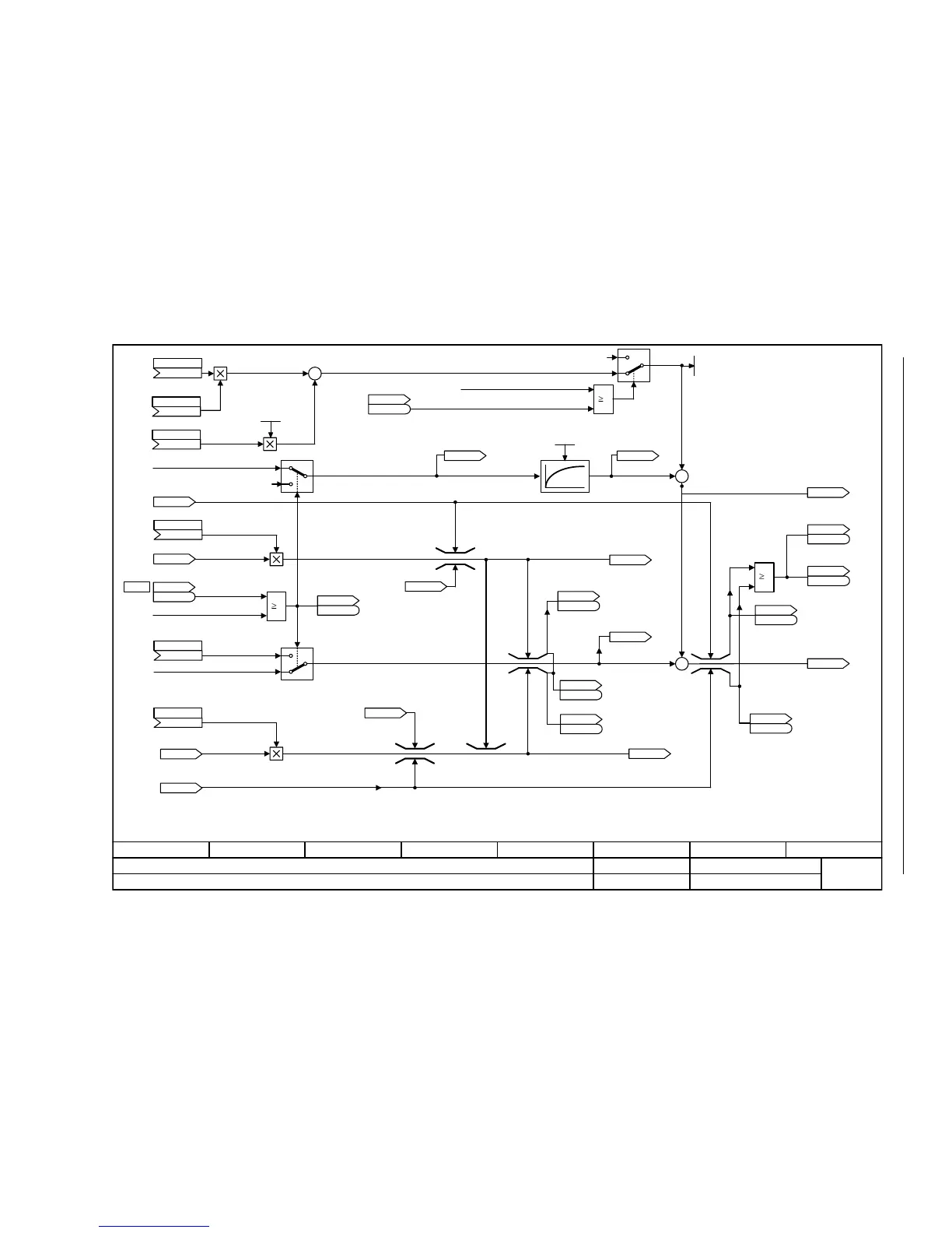
Fig. 2-77 6060 – Torque setpoint
- 6060 -
Function diagram
87654321
FP_6060_97_51.vsd
Vector control
G120 CU230P-2
13.12.2010 V4.4
Torque setpoint
1
p1300 = M
Reg
0
1
0
0
1
[6640.8]
[6030.1]
[6710.1]
[8012.1]
[2522.3]
[2522.3]
[6030.5]
[6640.8]
[2522.3]
[2522.3]
[2522.3]
+
+
+
+
[2520.7]
p1501
+
+
[6030.1]
[6722.1]
0
1
0
1
[6490.7]
<1>
<2>
<1>
<1><1> <2><2>
[6630.8]
[6630.8]
[6031.8]
1
[2526.2]
<3>
M_suppl 1
(0)
p1511 [C]
M_suppl 1 scal
(0)
p1512 [C]
M_suppl 2 scal
-2000.0 ... 2000.0 [%]
p1514 [D] (100.0)
M_suppl 2
(0)
p1513 [C]
Calculated accelerating torque
r1538
M_max upper eff [Nm]
STW n_ctrl
r1406
r1406
.12
(0)
p1503 [C]
0 = Speed control
1 = Torque control
M_set from the speed controller
r1539
M_max lower eff [Nm]
STW seq_ctrl
r0898
r0898
.8
The signal is only effective after magnetization has been
completed (r0056.4 = 1).
No pre-control if the Vdc controller is active [6220.8].
Acceleration control is inhibited for p1517 = 100 ms.
p1400.14 1 = Torque pre-control
1 = Speed controller enable
r1518
M_accel [Nm]
[0]
ZSW n_ctrl
r1407
r1407
.2
M_accel T_smooth
0.00 ... 100.00 [ms]
p1517 [D] (4.00)
r1518
M_accel [Nm]
[1]
ZSW n_ctrl
r1407
r1407
.8
r1508
M_set bef. M_suppl [Nm]
ZSW n_ctrl
r1407
r1407
.9
M_suppl total [Nm]
r1515
r1516
M_suppl + M_accel [Nm]
ZSW cl-loop ctrl
r0056
r0056
.13
ZSW n_ctrl
r1407
r1407
.7
ZSW n_ctrl
r1407
r1407
.8
r0079
M_set [Nm]
ZSW n_ctrl
r1407
r1407
.9
Torque limiting
r1538
M_max upper eff [Nm]
r1539
M_max lower eff [Nm]
[2501.7]
<4>
<3>
M_set is also influenced by the speed limit controller.
<4>
r1526
M_max up w/o offs [Nm]
r1527
M_max low w/o offs [Nm]
r1547
M_max outp n_ctrl [Nm]
[0]
r1547
M_max outp n_ctrl [Nm]
[1]
<5>
<5>
<5>
The connection to the source for the torque setpoint is
estabished automatically via the setting in p1500.
ZSW n_ctrl
r1407
r1407
.15
M_max low w/o offs
(1)
p1554 [C]
[6630.8]
M_max up w/o offs
(1)
p1552 [C]
[6040]

 Loading...


