- 3080 -
Function diagram
87654321
FP_3080_97_51.vsd
Setpoint channel
G120 CU230P-2
13.12.2010 V4.4
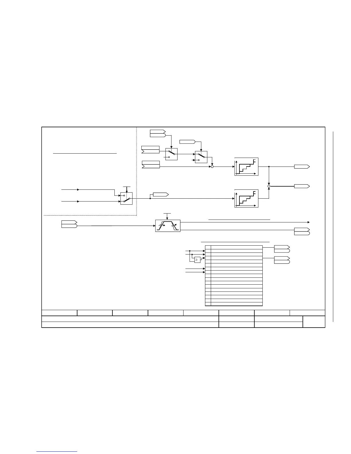
Ramp-function generator selection, status word, tracking
[6030.1]
[3060.8]
[3070.8]
1
Hochlaufgeber-Zustandswort
2
3
4
5
6
7
8
9
10
11
12
13
14
15
Bit
[3060.8]
[3070.8]
0
1
1
0
0
1
0
0
1
0
Hochlaufgeber freigeben (von STW Ablaufsteuerung)
r0898.4
<2>
+
+
[2501.7]
[2501.7]
x
y
+
+
<1>
<2>
xy
[3080.8]
[3050.8]
[2522.7]
[3060.1]
[3070.3]
<4>
<2>
<4>
<1>
(p2148)
t
x,y x
y
t
x,y x
y
T1
T1
[3060.8]
[3070.8]
<5>
<5>
Ramp-function generator selection
From the basic ramp-function generator
From the expanded ramp-function generator
n_set_4
n_set_5
Interpolator
Interpolator
Ramp-function generator tracking
Ramp flattening-off
Ramp-function generator status word
Ramp-up active
Ramp-down active
Ramp-function generator active
Ramp-function generator set
Ramp-function generator held
Ramp-function generator tracking active
Maximum limiting active
Reserved
Reserved
Reserved
Reserved
Reserved
Reserved
Reserved
Reserved
Reserved
For p1145 > 0, ramp-function generator tracking is activated when the torque limiting
responds. This means that the speed controller output only exceeds the torque limit by a
deviation that can be set via p1145.
For OFF1/OFF3, the ramp-function generator ramp is active. The ramp-function generator is
set to the setpoint (r1170)) and stops the drive with the ramp-downtime (p1121 or p1135).
STW1.4 (enable ramp-function generator) is effective while the drive is stopped via the
ramp-function generator. Depending on the p1115, the basic ramp-function generator [3060]
or the extended ramp-function generator [3070] is effective.
Behavior of the response ramp of the torque limiting:
p1145 = 0.0: No ramp-function generator tracking. The ramp-function generator ramp is no longer in the range of the
frequency actual value.
p1145 = 1.0: The ramp-function generator ramp remains as close as possible to the speed actual value.
p1145 > 1.0: The ramp-function generator ramp is steeper than for p1145 = 1.0 (higher "speed following error").
The value is displayed correctly only with r0899.2 = 1 (operation enabled)
ZSW n_ctrl
r1407
r1407
.7
RFG selection
p1115
STW seq_ctrl
r0898
r0898
.6
n_ctrl n_set 1
(0)
p1155 [C]
n_ctrl n_set 2
(0)
p1160 [C]
r1150
RFG n_set at outp [1/min]
RFG track intens
0.0 ... 50.0
p1145 [D] (0.0)
r1169
n_ctrl n_set 1/2 [1/min]
r1170
n_ctrl setp sum [1/min]
RFG ZSW
r1199
r1199
RFG ZSW
r1199
r1199
.2
RFG ZSW
r1199
r1199
.5
If technology controller is activated (p2200 > 0, p2251 = 1) connected with r2294.
<3>
<3>

 Loading...


