Function diagrams
Internal control/status words
2-558
© Siemens AG 2011 All Rights Reserved
SINAMICS G120 Control Units CU230P-2 Parameter Manual (LH9), 01/2011
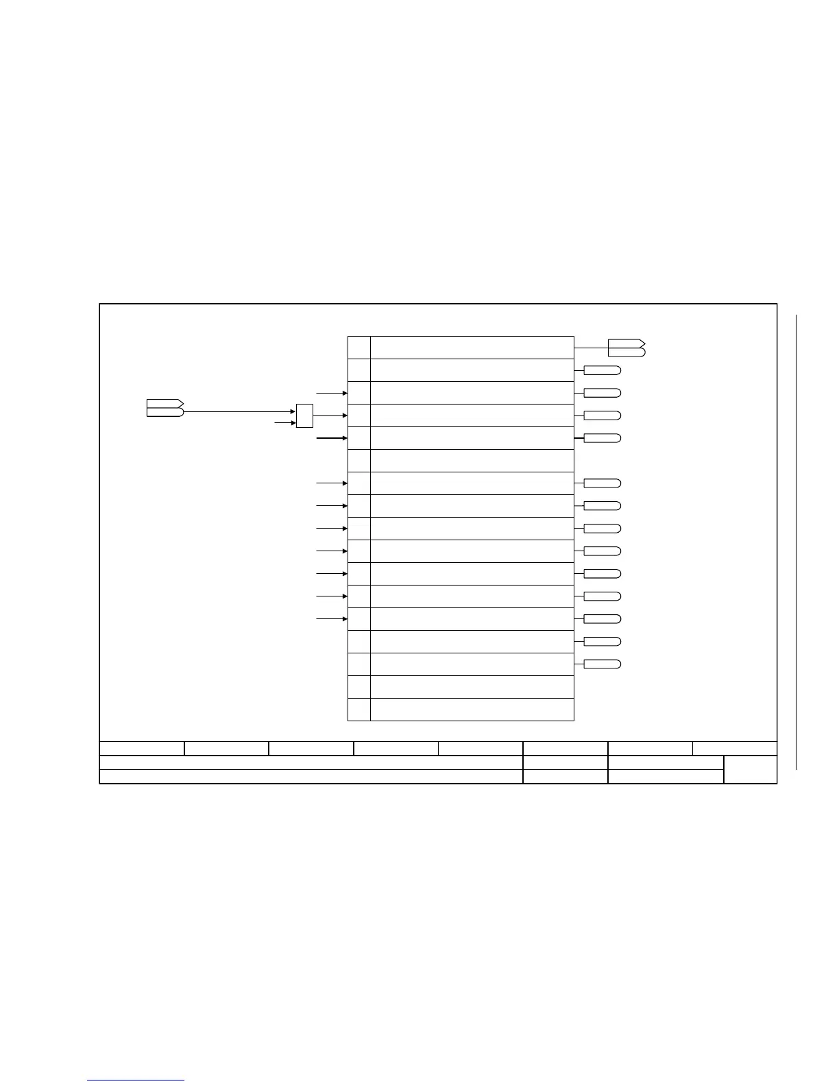
Fig. 2-52 2522 – Status word, speed controller
- 2522 -
Function diagram
87654321
FP_2522_97_51.vsd
Internal control/status words
G120 CU230P-2
13.12.2010 V4.4
Status word, speed controller
1
2
3
4
5
6
7
8
9
10
11
0
12
13
14
15
[2520.7]
r1407.8
r1407.9
r1407.11
r1407.1
r1407.7
r1407.10
r1407.11
r1407.5
r1407.6
r1407.2
r1407.3
r1407.12
r1407.13
r1407.0
&
From the changeover, closed-loop control types
1 = Torque control
Sensorless operation
From the control unit
Status word, speed controller (r1407)
Bit No.
1 = V/f control active
1 = Sensorless operation active
1 = Closed-loop torque control active
1 = Closed-loop speed control active
1 = Speed controller, I component held
1 = Speed controller, I component set
1 = Torque limit reached
1 = Torque limiting, upper, active
1 = Torque limiting, lower, active
1 = Droop enabled
1 = Speed setpoint limited
1 = Ramp-function generator set
1 = Sensorless operation due to a fault
Reserved
To speed setpoint, droop [6030.5]
To torque setpoint [6060.3]
Ramp-function generator tracking [3080.1]
Speed controller [6040.4]
Motor locked/stalled [8012.5]
From the speed setpoint, droop [6030.4][6030.5]
From the speed setpoint, droop [6030.3]
From the torque setpoint [6060.4] [6060.7]
From the torque setpoint [6060.7]
From the speed controller [6040.7]
From the speed controller [6040.7]
ZSW n_ctrl
r1407
r1407
Reserved
STW n_ctrl
r1406
r1406
.12
From the torque setpoint [6060.7]

 Loading...


