PLC diagnostics
13.1 Screen layout
Cylindrical grinding
360 Programming and Operating Manual, 07/2009, 6FC5398-4CP10-2BA0
13.1 Screen layout
The screen layout with its division into the main areas corresponds to the layout already
described in section "Software Interface".
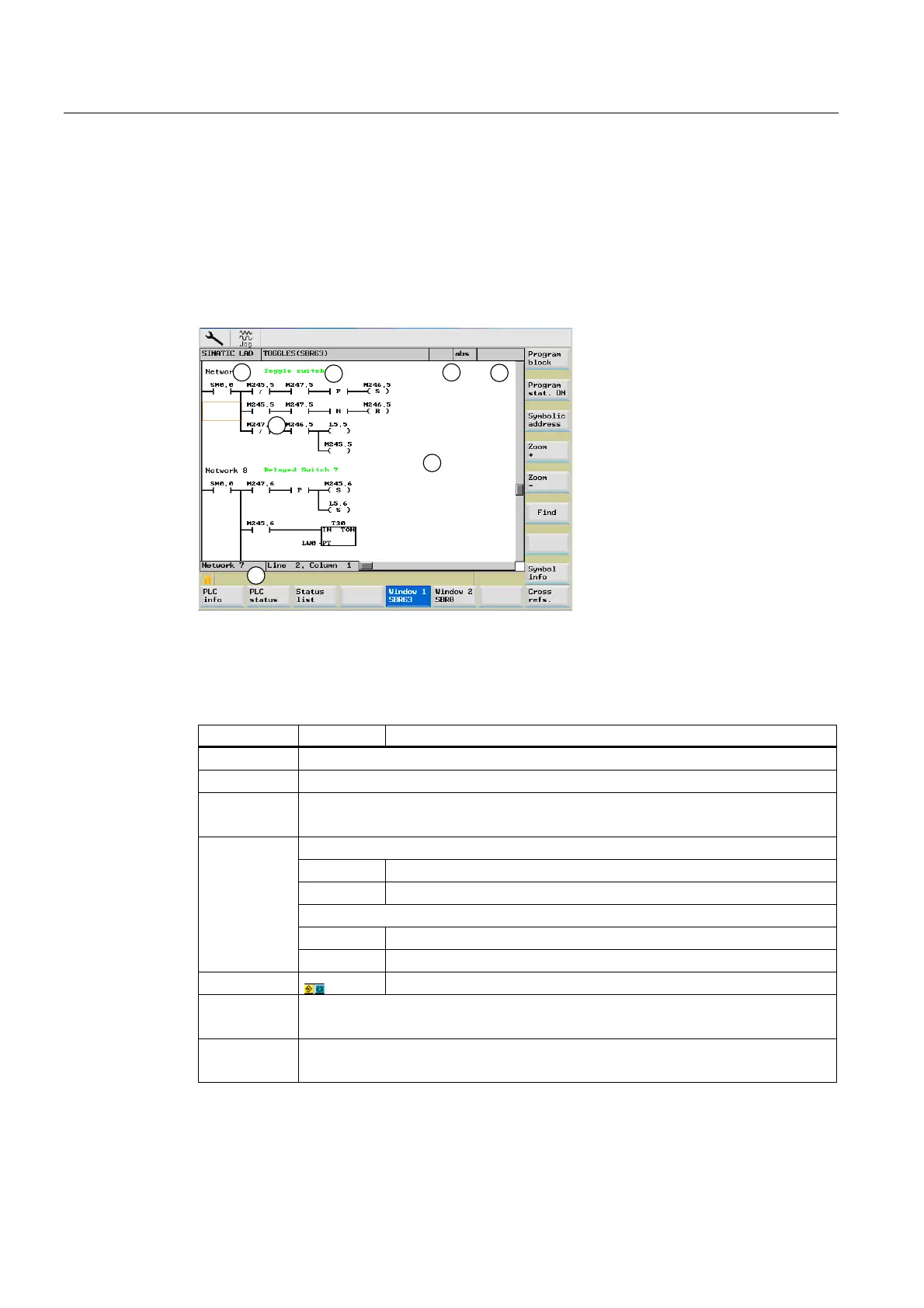
Any deviations and supplements pertaining to the PLC diagnostics are shown in the
following screen.
Figure 13-1 Screen layout
Table 13- 1 Key to screen layout
Screen item Display Meaning
① Application area
② Supported PLC program language
③ Name of the active program block
Representation: Symbolic name (absolute name)
Program status
RUN Program is running
STOP Program stopped
Status of the application area
Sym Symbolic representation
④
abs Absolute representation
⑤
Display of the active keys
⑥ Focus
Performs the tasks of the cursor
⑦ Tip line
contains notes for searching

 Loading...


