Appendix
A.2 Parameter tables of the tool data
Cylindrical grinding
380 Programming and Operating Manual, 07/2009, 6FC5398-4CP10-2BA0
A.2 Parameter tables of the tool data
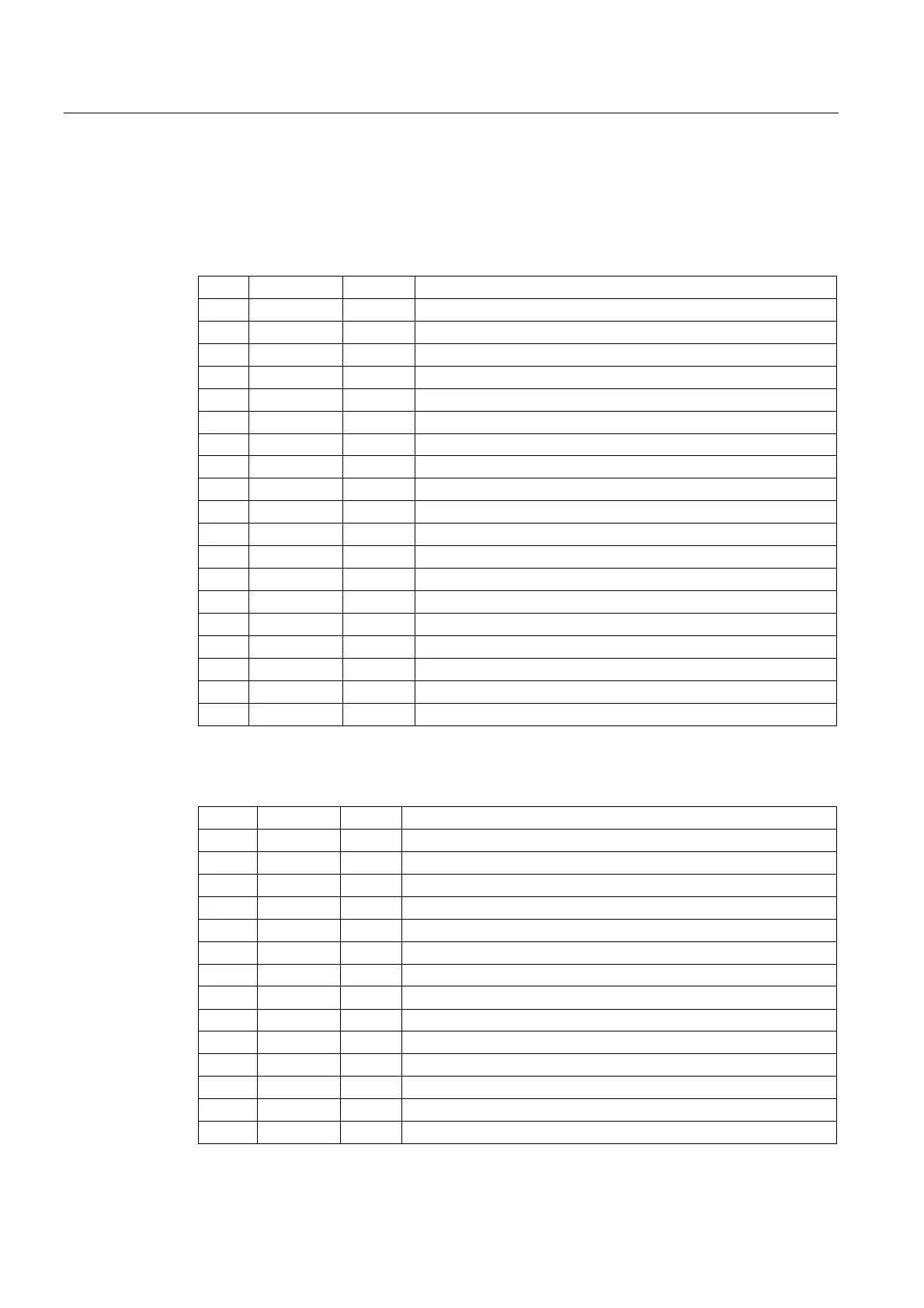
The following parameters, operated from the HMI, are available for the tool offsets.
Table A- 1 Grinding wheel data, x=[1...n] y=[1...6]
Tx TPG1 INT Spindle number
Tx TPG2 INT Concatenation rule = 0
Tx TPG3 REAL Min. wheel diameter
Tx TPG4 REAL Min. wheel width
Tx TPG5 REAL Current grinding wheel width
Tx TPG6 REAL Maximum speed
Tx TPG7 REAL Maximum GWPS
Tx TPG8 REAL Angle of inclined wheel
Tx TPG9 INT Parameter no. for radius calculation
Tx TPC1 REAL Wheel type (vertical, inclined, free)
Tx TPC2 REAL Amount of crown
Tx TPC3 REAL Dressing amount
Tx TPC4 REAL Cylindric compensation
Tx TPC5 REAL GWPS
Tx TPC6 REAL GWPS ratio
Tx TPC7 REAL Bypassing strategy (obstacle diameter)
Tx TPC8 REAL Basic cutting edge for dressing contour
Tx TPC9 REAL X shift
Tx TPC10 REAL Z shift
Table A- 2 1. Cutting edge 2. Cutting edge for left/right wheel edge for grinding wheel
Tx Dy DP1 INT Tool type=403
Tx Dy DP2 INT Cutting edge position (1...9)
Tx Dy DP3 REAL D - Diameter of the new wheel
Tx Dy DP4 REAL L - Distance of the wheel reference point
Tx Dy DP5 REAL (reserved, length 3)
Tx Dy DP6 REAL R - Tool nose radius
Tx Dy DP7 REAL Dressing amount (µm) left/right
Tx Dy DP8 REAL Dresser wear X (µm) left/right
Tx Dy DP9 REAL Dresser wear Z (µm) left/right
Tx Dy DP10 REAL Path feedrate (mm/rev), left/right
Tx Dy DP11 REAL Path feedrate X (mm/rev), left/right
Tx Dy DP12 REAL dD - Change in diameter (dressing amount X)
Tx Dy DP13 REAL dL - Change in distance (dressing amount Z)
Tx Dy DP14 REAL (Length 3)
Tx Dy DP15 REAL dR - Change in tool nose radius (radius wear)

 Loading...


