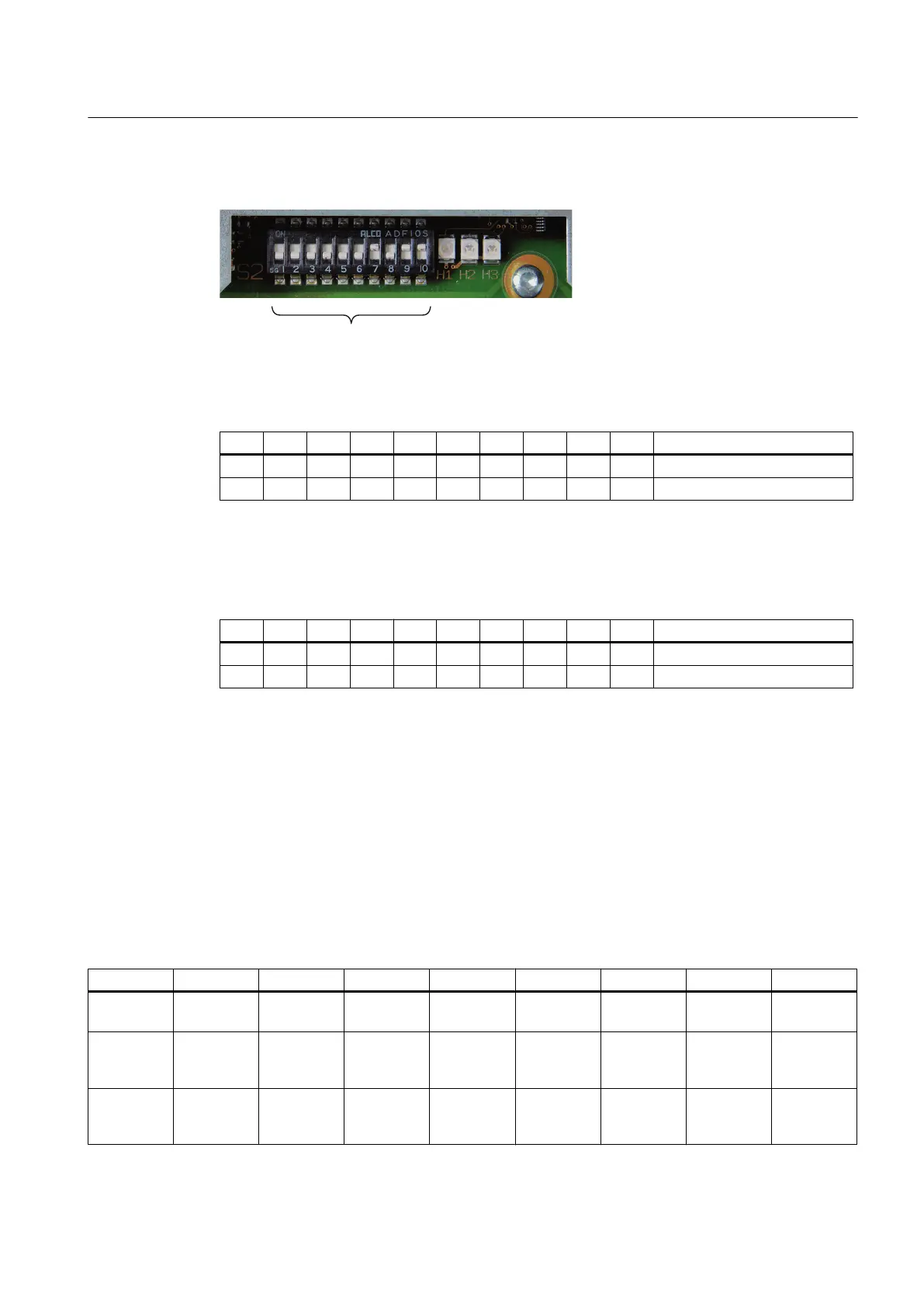
Switch S2
Switch position: "ON" is at the top.
Table 7-26 Switch S2 is set as delivered
1 2 3 4 5 6 7 8 9 10 Meaning
ON ON PLC I/O Interface
OFF OFF OFF OFF OFF OFF OFF OFF PROFINET address "0"
The two switches S2-9 and S2-10 must remain set to "ON".
The switches S2-1 to S2-8 define the PROFINET address. For a SINUMERIK 828D,
the address "64" must always be assigned to the MCP.
Table 7-27 Settings of switch S2
1 2 3 4 5 6 7 8 9 10 Meaning
ON ON ON
OFF OFF OFF OFF OFF OFF OFF PROFINET address "64"
7.2.4 Parameterization
The specifications for assigning input and output bytes listed in the tables are set as standard
addresses in the PLC by setting the following machine data:
MD12986 PLC_DEACT_IMAGE_LADDR_IN[6] = -1
Standard input image
Table 7-28 Input image MCP 310C PN
Byte Bit7 Bit6 Bit5 Bit4 Bit3 Bit2 Bit1 Bit0
EB112 * NC
Stop Spindle -
Spindle
100% Spindle +
Single
block JOG MDA AUTO
EB113 NC
Start
Spindle
right
* Spindle
stop
Spindle
left
Keyswitch
position 3
REF REP Teach
IN
EB114 Feed
Start
* Feed
Stop
INC VAR Keyswitch
position 0
INC 1000 INC 100 INC 10 INC 1
Connectable components
7.2 MCP 310C PN
PPU
Manual, 01/2014, 6FC5397-2DP40-3BA3 123

 Loading...


