6.5.2 Example: Connecting an inductive proximity switch (BEROs)
Boundary conditions
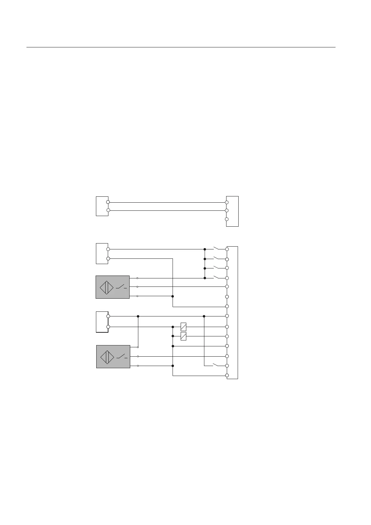
When connecting a BERO the following rules must be observed:
● BEROs can always be connected to each input.
● Because both the DI input terminals as well as the parameterizable DI/DO terminals are
isolated, the ground of the supply must be connected to the associated M terminal.
● When a connection is made to one of the parameterizable terminals, the positive pole of
the power supply must also be connected to the associated P connection terminal.
● Each group can be supplied with its own supply that is independent of the device supply.
In the simplest case can, however, everything can be fed from a single supply.
Nevertheless, all M and P terminals must be connected.
9'&
([WSRZHUVXSSO\
,QSXWFRQWDFW
,QSXWFRQWDFW
,QSXWFRQWDFW
,QSXWFRQWDFW
,QSXW%(52
,QSXWFRQWDFW
,QSXW%(52
,QSXWIUHH
2XWSXW
2XWSXW
9'&
9'&
0
3
;
;
',
',
',
',
',
',
0
3
','2
','2
0
','2
','2
0
3
0
0
3
%1
%.
%8
%1
%.
%8
BK (black) Signal
BU (blue) - supply
BN (brown) + supply
Figure 6-5 Connection to X122
Interface description
6.5 Digital inputs/outputs
PPU
82 Manual, 01/2014, 6FC5397-2DP40-3BA3

 Loading...


