The cycle time of the analog value accumulation is limited by the PLC cycle.
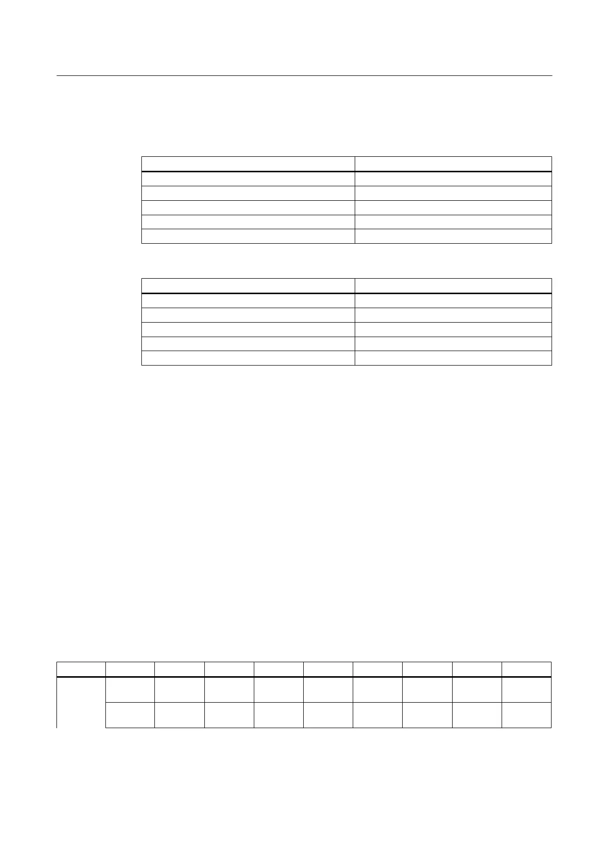
Table 7-96 Technical specifications in the "voltage output" operating mode
Parameter Value
Output range (rated value) - 10 V to + 10 V
Permitted overrange - 10.5 V to + 10.5 V
Resolution 16 bits (including sign)
Accuracy +/- 0.5%
Max. load current -3 mA to +3 mA
Table 7-97 Technical specifications in the "current output" operating mode
Parameter Value
Output range (rated value) - 20 mA to + 20 mA
Permitted overrange - 20.2 mA to + 20.2 mA
Resolution 16 bits (including sign)
Accuracy +/- 0.5%
Load impedance ≤ 600 ohm
7.7.4 Assigning parameters
7.7.4.1 Input / output images
Input image
The image comprises 3 slots (n, m, d ≙ start address, see Addressing the I/O modules
(Page 75)):
● Slot 1: Digital inputs (DI)
– n+0 … n+8 (9 byte)
– X222.P3 - .P10 are rapid inputs
● Slot 2: 2 analog inputs (AI): m+0 … m+7 (8 byte)
● Slot 3: Diagnostics: d+0 .. d+1
Table 7-98 Input image of digital inputs for the 1st I/O module (n=0)
Terminal Byte Bit7 Bit6 Bit5 Bit4 Bit3 Bit2 Bit1 Bit0
X111
n+0 Pin10
DI 0.7
Pin9
DI 0.6
Pin8
DI 0.5
Pin7
DI 0.4
Pin6
DI 0.3
Pin5
DI 0.2
Pin4
DI 0.1
Pin3
DI 0.0
n+1 Pin18
DI 1.7
Pin17
DI 1.6
Pin16
DI 1.5
Pin15
DI 1.4
Pin14
DI 1.3
Pin13
DI 1.2
Pin12
DI 1.1
Pin11
DI 1.0
Connectable components
7.7 PP 72/48D 2/2A PN
PPU
Manual, 01/2014, 6FC5397-2DP40-3BA3 203

 Loading...


