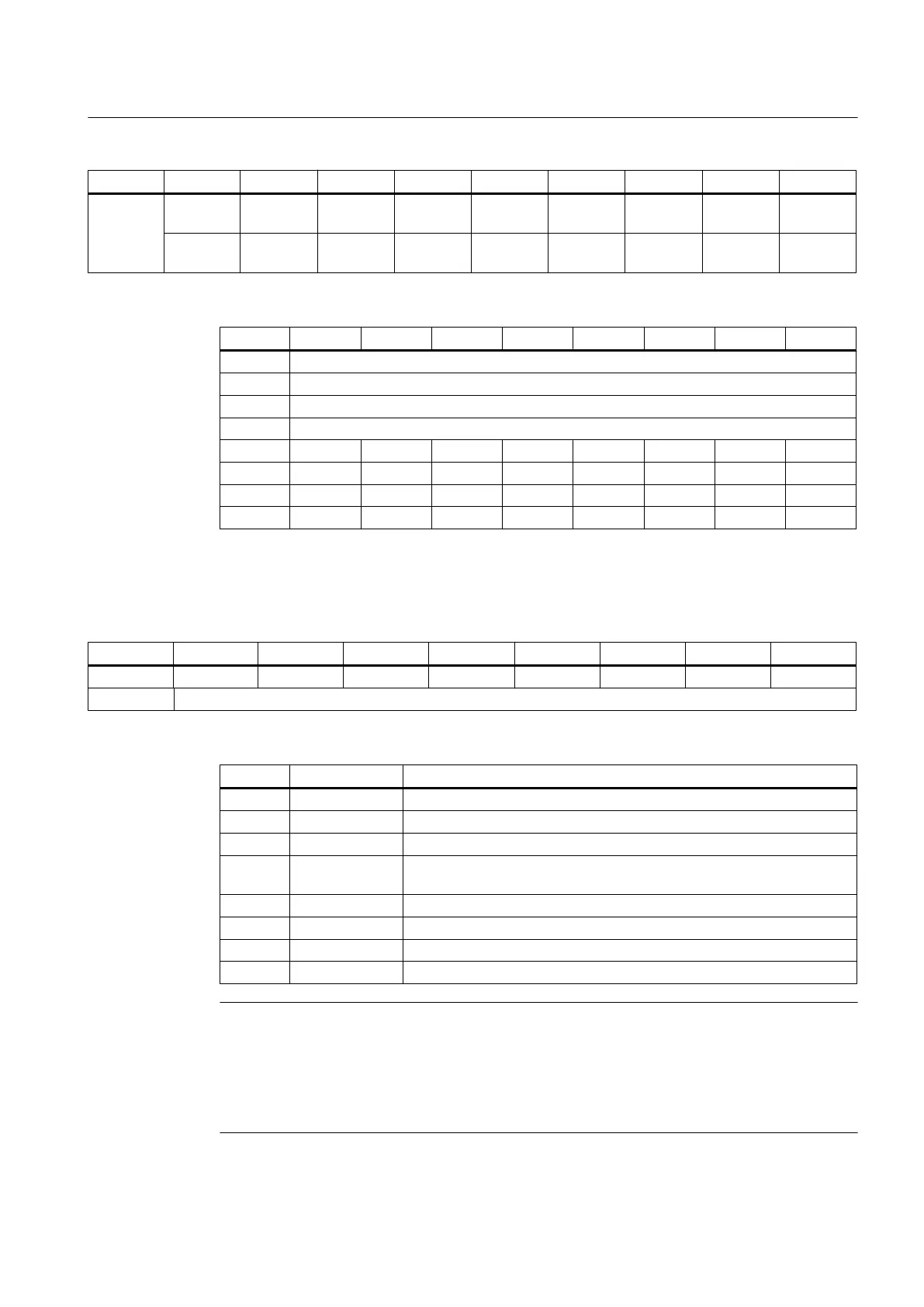
Terminal Byte Bit7 Bit6 Bit5 Bit4 Bit3 Bit2 Bit1 Bit0
X333
n+4 Pin38
DO 4.7
Pin37
DO 4.6
Pin36
DO 4.5
Pin35
DO 4.4
Pin34
DO 4.3
Pin33
DO 4.2
Pin32
DO 4.1
Pin31
DO 4.0
n+5 Pin46
DO 5.7
Pin45
DO 5.6
Pin44
DO 5.5
Pin43
DO 5.4
Pin42
DO 5.3
Pin41
DO 5.2
Pin40
DO 5.1
Pin39
DO 5.0
Table 7-101 Output image of analog outputs for the 1st I/O module (m=56)
Byte Bit7 Bit6 Bit5 Bit4 Bit3 Bit3 Bit1 Bit0
m+0 Analog Control Byte 0
m+1 Analog Control Byte 1
m+2 Analog Control Byte 2
m+3 Analog Control Byte 3
m+4 AO 0.15 AO 0.14 AO 0.13 AO 0.12 AO 0.11 AO 0.10 AO 0.9 AO 0.8
m+5 AO 0.7 AO 0.6 AO 0.5 AO 0.4 AO 0.3 AO 0.2 AO 0.1 AO 0.0
m+6 AO 1.15 AO 1.14 AO 1.13 AO 1.12 AO 1.11 AO 1.10 AO 1.9 AO 1.8
m+7 AO 1.7 AO 1.6 AO 1.5 AO 1.4 AO 1.3 AO 1.2 AO 1.1 AO 1.0
7.7.4.2 Diagnostics via input image
Table 7-102 Diagnostics input image
Byte Bit7 Bit6 Bit5 Bit4 Bit3 Bit3 Bit1 Bit0
d+0 count_2 count_1 count_0 T_Alarm_2 T_Alarm_1 Diag_2 Diag_1 Diag_0
d+1 Status_1
Table 7-103 Messages in byte 0
Bit Signal name Message
7 count_2 alive and well 2
6 count_1 alive and well 1
5 count_0 alive and well 0
4 T_Alarm_2 Temperature not within the operating temperature range defined for the
module
3 T_Alarm_1 Critical temperature exceeded
2 Diag_2 Overload DO byte 5/4
1 Diag_1 Overload DO byte 3/2
0 Diag_0 Overload DO byte 1/0
Note
The "alive and well" counter is a 3 bit modulo counter on a PP application level. The PP
application can be monitored using this counter. Failure of the application software does not
generally result in a communication failure, as this is developed in a hardware-supported
manner. The watch dog switches off the digital outputs, while the inputs remain at their last
set values.
Connectable components
7.7 PP 72/48D 2/2A PN
PPU
Manual, 01/2014, 6FC5397-2DP40-3BA3 205

 Loading...


