7.7.4.5 Examples
The following examples for assigning parameters to analog inputs / outputs are provided for
the I/O module with device number "7".
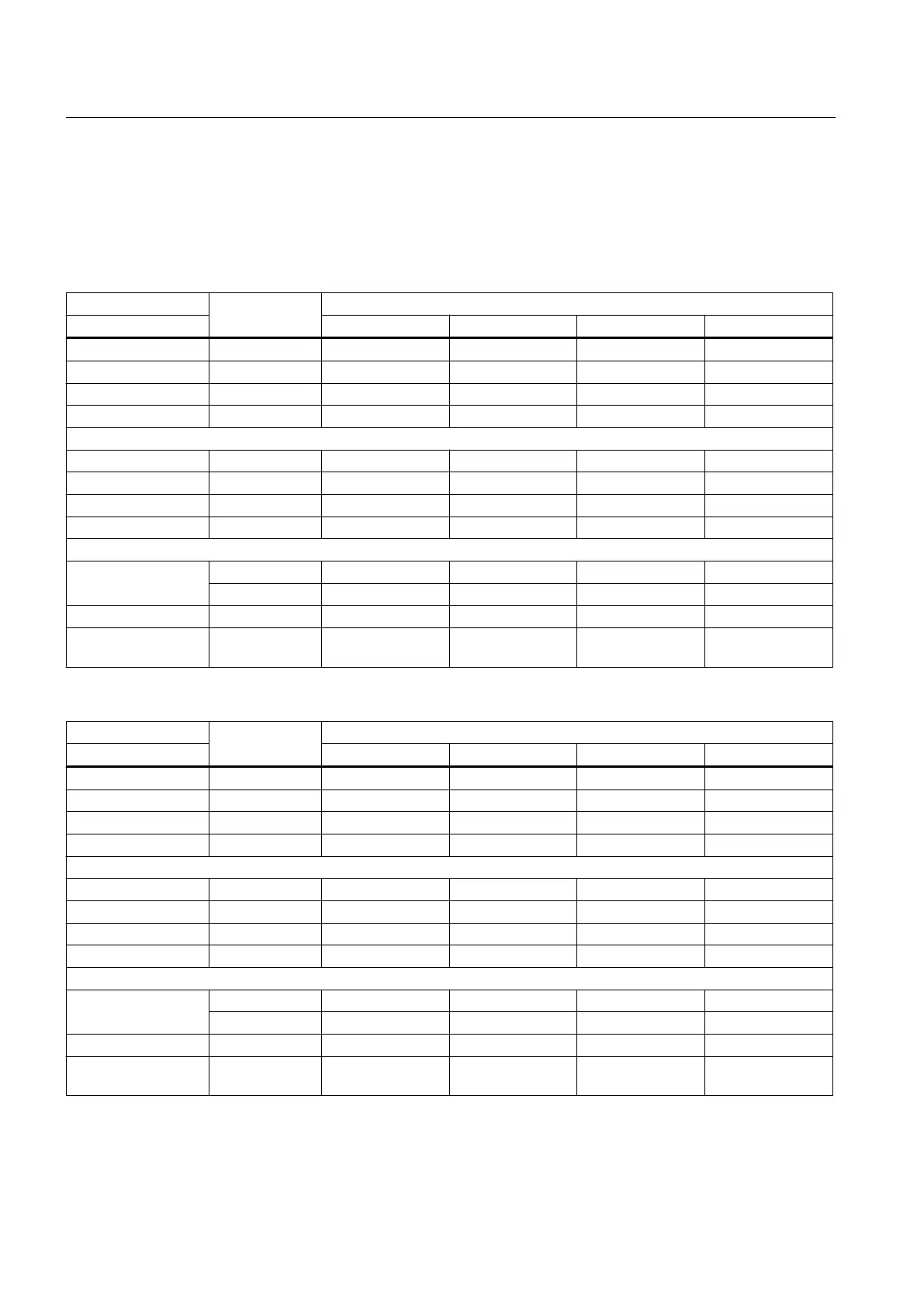
Table 7-112 Measured values and responses in the voltage measurement operating mode
Address Voltage ±10 V
0 V 2.5 V 10 V 12 V
Operating mode QB72 16#55 16#55 16#55 16#55
Format QB73 16#1 16#1 16#1 16#1
Value QW76 16#0 16#199B 16#6666 16#7AE1
Value QW78 16#0 16#199B 16#6666 16#7AE1
Operating mode IB72 16#55 16#55 16#55 16#55
Format IB73 16#1 16#1 16#1 16#1
Value IW76 16#0 16#66D 16#19B5 16#0
Value IW78 16#0 16#66D 16#19B5 16#0
Diagnostics IB50 - - - 16#2
IB51 16#0 16#0 16#0 16#7
PNFault LED off off off on
Troubleshooting Deactivating/
activating
Table 7-113 Measured values and responses in the current measurement operating mode
Address Current 20 mA
0 mA 5 mA 20 mA 22 mA
Operating mode QB72 16#AA 16#AA 16#AA 16#AA
Format QB73 16#1 16#1 16#1 16#1
Value QW76 16#0 16#199B 16#6666 16#70A5
Value QW78 16#0 16#199B 16#6666 16#70A5
Operating mode IB72 16#AA 16#AA 16#AA 16#AA
Format IB73 16#1 16#1 16#1 16#1
Value IW76 16#0 16#665 16#1996 16#0
Value IW78 16#0 16#665 16#1996 16#0
Diagnostics IB50 - - - 16#2
IB51 16#0 16#0 16#0 16#7
PNFault LED off off off on
Troubleshooting Deactivating/
activating
Connectable components
7.7 PP 72/48D 2/2A PN
PPU
212 Manual, 01/2014, 6FC5397-2DP40-3BA3

 Loading...


