Note
If your axis grouping contains a Smart Line Module without DRIVE-CLiQ (5 kW or 10 kW),
you must assign the Smart Line Module enabling signal to the X122.1 digital input on the
PPU.
Definition
The abbreviations used in "Signal type" column in the tables showing the pin assignment have
the following meaning:
B Bidirectional
GND Grounding
I Input
O Output
VI Voltage input (supply voltage)
VO Voltage output (supply voltage)
6.2 Power supply connection
6.2.1 Requirements for the power supply
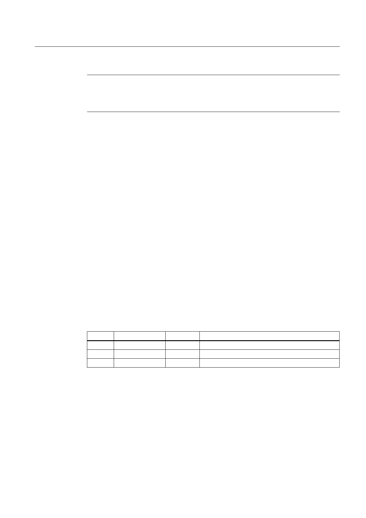
Pin assignment at X1 screw-type terminal block
Table 6-1 Pin assignment
Pin Signal name Signal type Meaning
1 P24 VI 24 VDC power supply
2 M VO Ground
3 PE GND Protective ground
Requirements of DC power supplies
Interface X1 is intended exclusively for the connection of the external 24 V power supply, e.g.
● SITOP (stabilized 24 V power supplies)
● CSM (Control Supply Module)
The following power consumption values for the PPU provide a configuration basis for
calculating the 24 VDC power supply.
Interface description
6.2 Power supply connection
PPU
Manual, 01/2014, 6FC5397-2DP40-3BA3 69

 Loading...


