Name Color Status Meaning
Activity Yellow Lit Sending or receiving
Off No activity
PROFINET address (S1)
The right logical address must be assigned to the I/O module for communication with PLC I/O
interface using the 10 bit DIP switch S1.
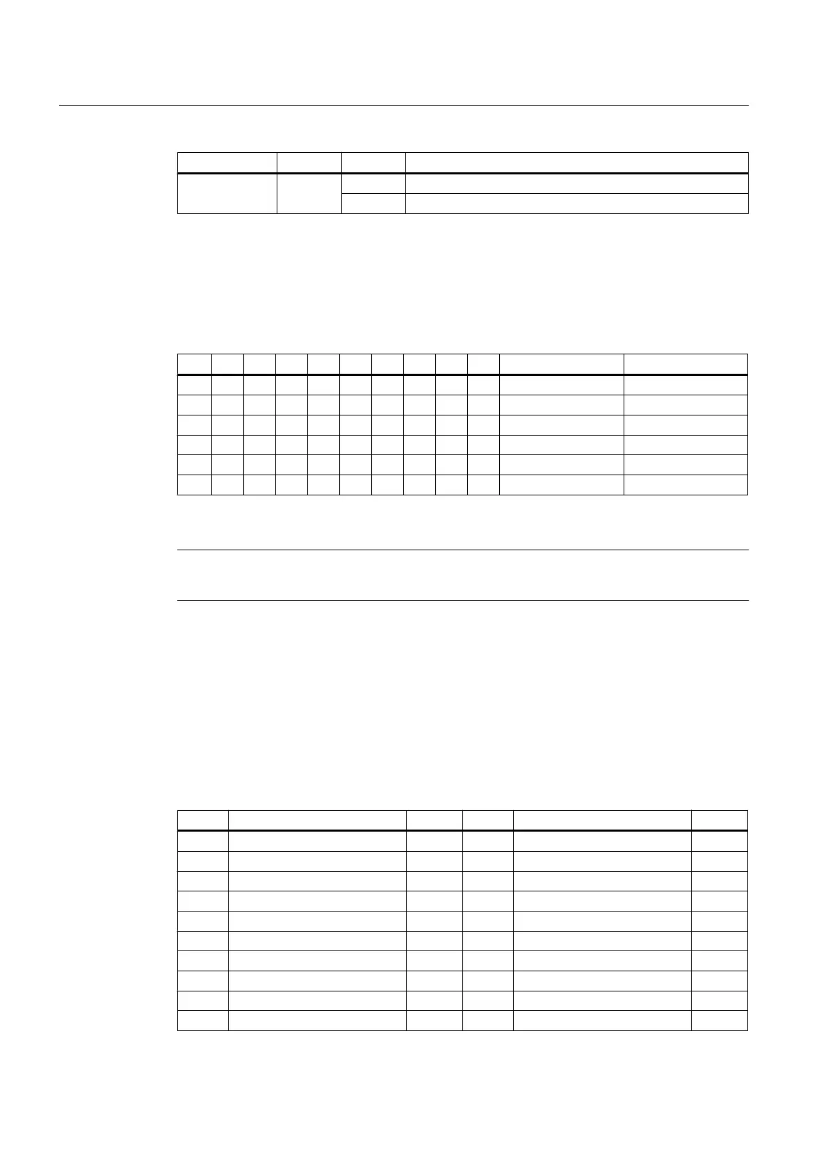
Table 7-66 Switch S1 settings
1 2 3 4 5 6 7 8 9 10 Device name Meaning
on on
on off off on off off off off pp72x48pn9 1. PP module
off off off on off off off off pp72x48pn8 2. PP module
on on on off off off off off pp72x48pn7 3. PP module
off on on off off off off off pp72x48pn6 4. PP module
on off on off off off off off pp72x48pn5 5. PP module
The device name consists of the PROFINET name and the device number: in the case of I/O modules,
the 1st module is device number 9.
Note
A newly set PROFINET address will only come into effect after power OFF/ON.
The switch positions 9 and 10 guarantee the PROFINET functionality of the module and must
always be switched "on".
7.6.3.3 X111, X222 and X333 pin assignment
Pin assignment
Table 7-67 Pin assignment X111
Pin Signal name Type Pin Signal name Type
1 M GND 2 P24OUT VO
3 DI 0.0 I 4 DI 0.1 I
5 DI 0.2 I 6 DI 0.3 I
7 DI 0.4 I 8 DI 0.5 I
9 DI 0.6 I 10 DI 0.7 I
11 DI 1.0 I 12 DI 1.1 I
13 DI 1.2 I 14 DI 1.3 I
15 DI 1.4 I 16 DI 1.5 I
17 DI 1.6 I 18 DI 1.7 I
19 DI 2.0 I 20 DI 2.1 I
Connectable components
7.6 PP 72/48D PN
PPU
174 Manual, 01/2014, 6FC5397-2DP40-3BA3

 Loading...


