6.5.3 Technical data
Note
An open input is interpreted as "low".
Note
Terminals MEXT1 ... MEXT4 must be connected for the digital inputs/outputs to function. This
can be done as follows:
● Connect the ground reference of the digital inputs.
● A jumper to terminal M on plug connector X1.
P24EXT (P1, P3) must also be connected so that the outputs function. An external supply
can also be connected here, or a jumper can be inserted to terminal P at X1.
This removes the galvanic isolation for these digital inputs.
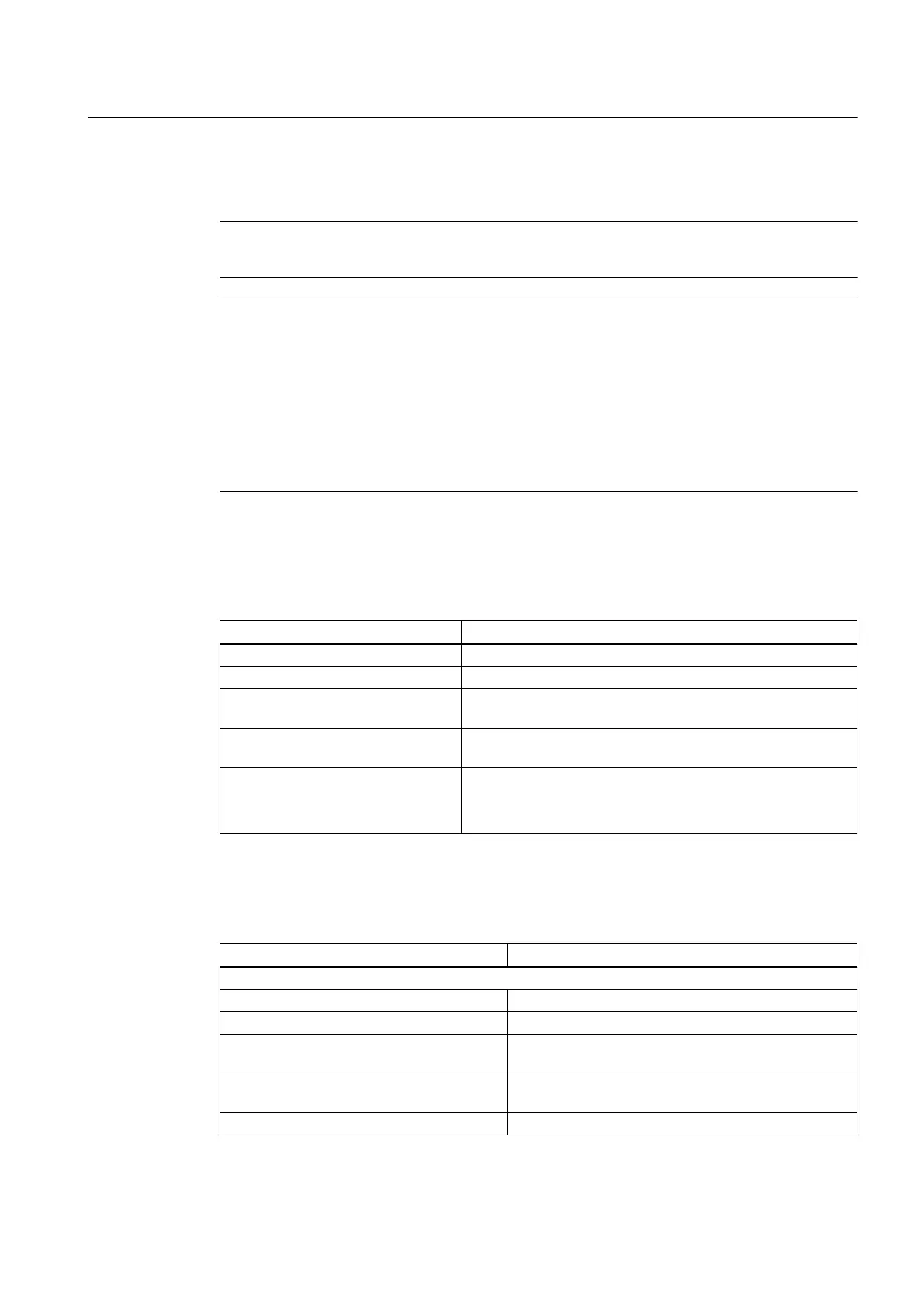
Digital inputs
Table 6-6 Technical data of the digital inputs at X122/X132 and X242/X252
Parameter Value
Voltage -3 V to 30 V
Typical power consumption 10 mA at 24 V DC
Signal level (including ripple) High: 15 V to 30 V
Low: -3 V to 5 V
Signal propagation times L → H: 50 μs
H → L: 150 μs
Galvanic isolation Yes:
The reference potential is terminal 2M at X122/X132.
The reference potential is terminal 4M at X242/X252.
Digital inputs/outputs
Table 6-7 Technical data of the digital inputs/outputs at X122/X132
Parameter Value
As input:
Voltage -3 V to 30 V
Typical power consumption 10 mA at 24 V DC
Signal level (including ripple) High: 15 V to 30 V
Low: -3 V to 5 V
Signal propagation (rapid inputs) L → H: 10 μs
H → L: 150 μs
Galvanic isolation Yes: The reference potential is terminal 1M.
Interface description
6.5 Digital inputs/outputs
PPU
Manual, 01/2014, 6FC5397-2DP40-3BA3 83

 Loading...


