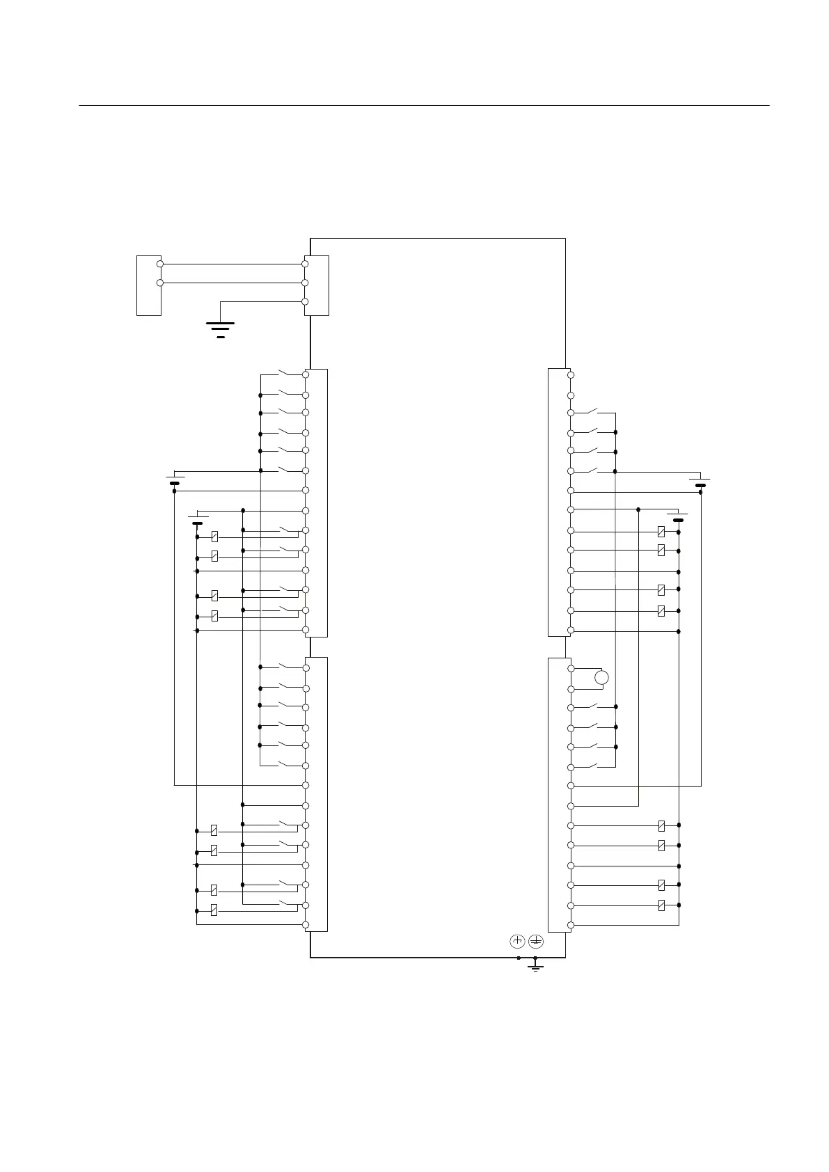
6.5.1 Terminal connection diagram
The following figure shows the terminal connection diagram for the digital inputs/outputs of a
PPU.
'&9
'&9
9
,1
,1
,1
,1
0
3
2
2
0
2
2
0
;
$2
$0
,1
,1
,1
,1
0
3
2
2
0
2
2
0
9'&
([WSRZHUVXSSO\
9'&
9'&
5DSLGLQSXWVPXVWEH
VKLHOGHG
3(
0
1&,2
'ULYH,2
;
3
',
',
',
',
',
',
0
3
,2
,2
0
,2
,2
0
;
',
',
',
',
',
',
0
3
,2
,2
,2
0
,2
0
;
338
;
Figure 6-4 Terminal connection diagram for digital inputs/outputs
Interface description
6.5 Digital inputs/outputs
PPU
Manual, 01/2014, 6FC5397-2DP40-3BA3 81

 Loading...


