Value
byte 1
Cause Effect Remedy
6 Overrange at the inputs Check input circuit and adjust, if required.
7 Overrange at the outputs Correct values in the user program.
1)
The analog outputs retain their last specified value.
Diagnostics via Status Bytes 0/1
In Status Byte 0, the set operating modes are reflected e.g. "0x55" if Control Byte 0 = 0x55
has been specified.
In the event of an error, the error bit is set in Status Byte 1 (bit 7). In the event of an error in
one channel, all channels are disabled.
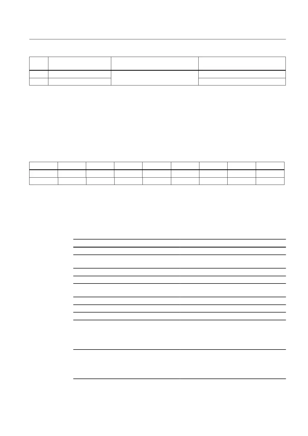
Table 7-79 Input image of analog inputs (excerpt)
Byte Bit7 Bit6 Bit5 Bit4 Bit3 Bit3 Bit1 Bit0
m+0 0 0 0 0 0 0 0 0
m+1 Error bit 0 0 0 0 0 0 0
7.6.5 Technical data
PP 72/48D PN I/O module
Parameter Value
Input voltage 24 V DC + 20% / - 15%
Power consumption at rated load
(without digital outputs)
17 W
Degree of protection in acc. with EN 60529 IP00
Protection class in acc. with EN 61800-5-1 III; DVC A (PELV)
Shock load during transportation (in transportation
packaging)
Free-fall ≤ 1 m
Approvals CE, cULus
Cooling Open-circuit ventilation
Condensation Not permitted
Limits for relative humidity at 25 °C:
● Storage
● Transportation
● Operation
5 ... 95% without condensation
5 ... 95% without condensation
5 ... 90% without condensation
Temperature limits:
● Storage
● Transportation
● Operation
-40 ... 70 °C
-40 ... 70 ℃
0 ... 55 °C
Connectable components
7.6 PP 72/48D PN
PPU
Manual, 01/2014, 6FC5397-2DP40-3BA3 183

 Loading...


