20
5
Electrical Connection
5.1 Safety Instructions
Incorrect cable connection may cause device damage or even personal injury.
All cables must be intact, well insulated, appropriately dimensioned, and firmly
connected.
5.2 Port Introduction
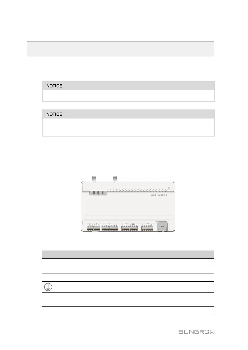
External wiring terminals are located at the bottom of Logger1000, and the wiring area is
shown in the figure below.
figure 5-1 Wiring area
table 5-1 Port description
Port Function
Description
24V OUT
24V power output 24V±5%, the max. output current: 0.5A
DI Converters AI into DI
Switch for enabling the AI/DI function
24V IN
24V power input
24V±3%
Grounding Connecting protective grounding cable
AI/DI
Compatible with AI/DI
function
Default AI input sampling: 0-10V or 4-
20mA
DI
Digital input Digital signal input

 Loading...

