23
5.3.1.2 RJ45 port connection
Communication cable specification:
Cable Type
RJ45 communication cable Shielded twisted pair Ethernet cable
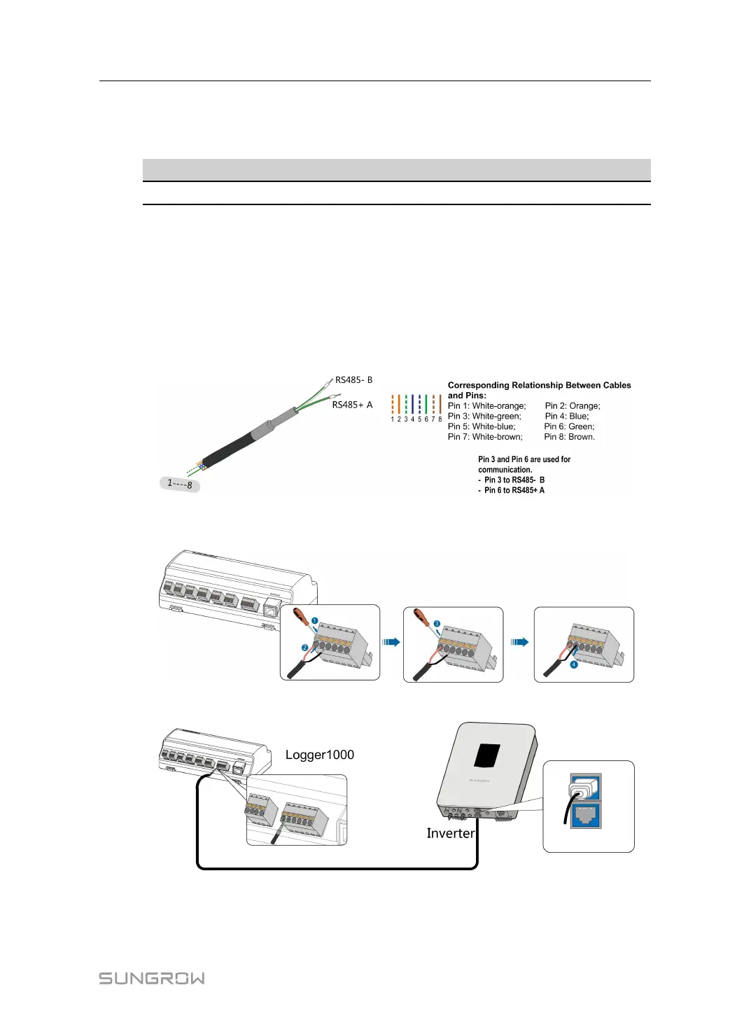
Step 1 Lead the RJ45 communication cable from the inverter to the wiring area of Logger1000.
Step 2 Strip the insulation layer of the communication cable with an Ethernet wire stripper, and lead
the corresponding RS485A/B signal cables out. Insert cord end terminals into signal cable
RS485+ A and signal cable RS485- B, and crimp them with a crimper. Cut off the redundant
signal cable and warp it with a heat-shrink tubing.
If the communication cable is Shielded Ethernet cable, white-green wire 3 is defined as
RS485- B wire and the green wire 6 as RS485+ A wire.
Step 3 Connect the communication cable to the RS485 ports of the Logger1000, as shown in the fig-
ure below.
Step 4 Connect the Logger1000 to the inverter.
- - End
User Manual 5 Electrical Connection

 Loading...

