31
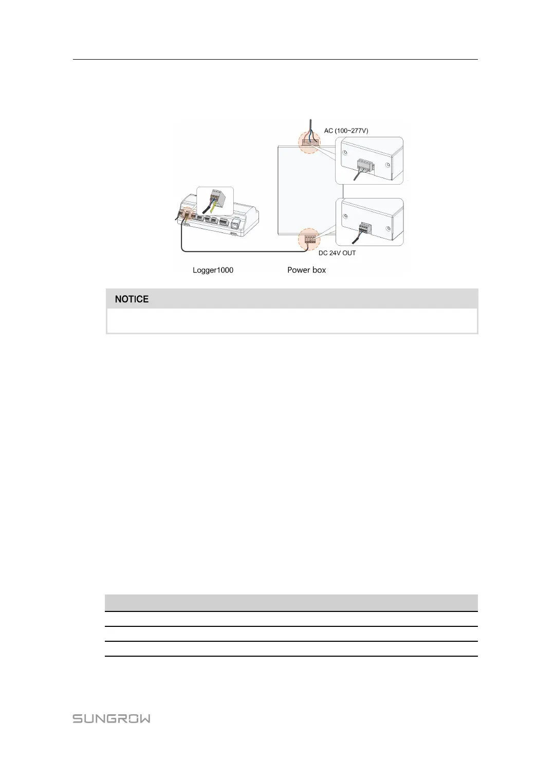
Step 4 Connect the DC cable led from the "24V IN" port of the Logger1000 to the "DC 24V OUT"
port of the power box. Connect the stripped AC cable to the "AC (100~277V)" port of the
power box, and connect the other end of the AC cable to the 220V AC power.
The power source should meet limited power source or PS2 requirements.
- - End
5.7 Cable Routing Requirements
Cables used in the system generally include power cables and communication cables.
The communication cable needs to be routed away from the power cable, and the cables
need to form a right angle at the intersection. The communication cable needs to be as short
as possible and keeps a distance from the power cable.
Power cables and communication cables should be routed in different cable trenches to
avoid long-distance parallel cable routing of power cables and other cables, thereby reduc-
ing electromagnetic interference due to output voltage transient.
The distance between the power cable and communication cable should be greater than
200mm. When the cables meet with each other, the cross angle should be 90°, and the dis-
tance can be reduced accordingly.
The following table shows the recommended minimum distances between parallel shielded
communication cables and power cables.
Parallel cable length (m) Min. distance (m)
200 0.3
300 0.5
500 1.2
The communication cables should be routed as closely to the ground surface or supports
(such as support beam, steel channel, or metal rail) as possible.
User Manual 5 Electrical Connection

 Loading...

