71
table 8-2 Analog control interface signal definition
Signal Definition
1+,1-,2+,2-,3+,3-,4+,4- 4 analog input channels
The Logger1000 supports 4 inputs of 4~20mA analog currents or 4 inputs of 0~10V analog
voltage.
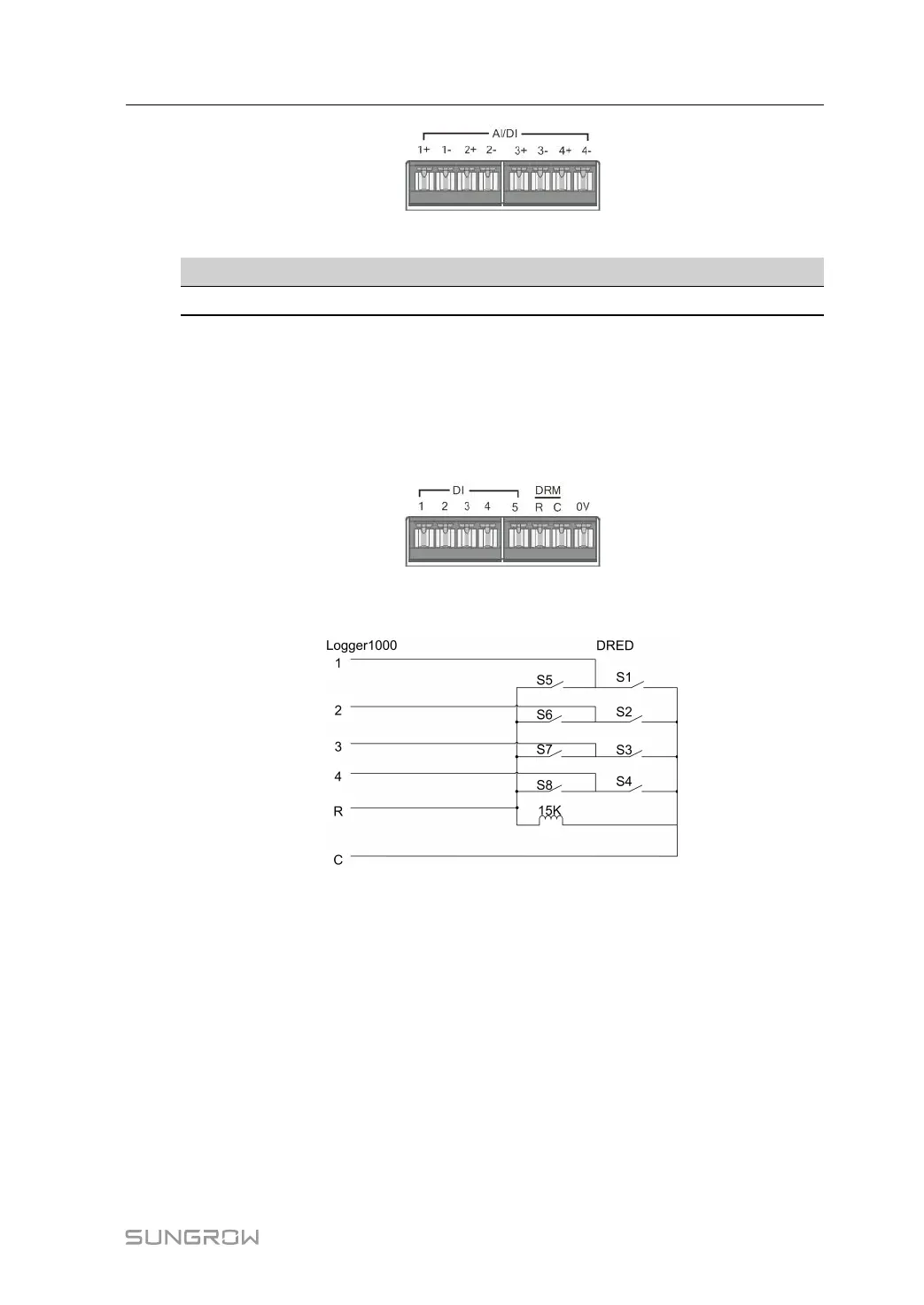
8.2.3 DRM Control Interface
The DRM control interface are located at the bottom of the Logger1000, as shown in the fig-
ure below.
The DRM interface works together with DI1~DI4 to achieve the DRM function.
Wiring between the Logger1000 and the DRED is as follows:
The DRM interface requires that the Logger1000can be connected to the DRED via the cor-
responding wiring terminal or RJ45 connector.
8.3 Power Control
Power regulation includes active power control and reactive power regulation.
8.3.1 Active Power
8.3.1.1 Disable Derating
If the inverter needs to operate at full load, the active control mode should be set to Disable
Derating.
Step 1 Click “Power control→Active power” to enter the active power interface.
User Manual 8 Grid Dispatching Function

 Loading...

