Rear Suspension: 2C-3
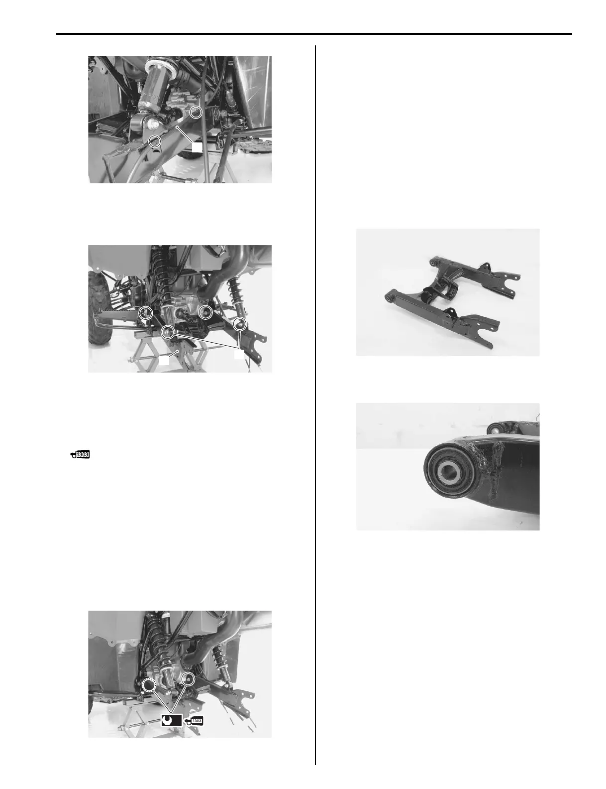
6) Remove the rear shock absorber lower mounting
bolts (2).
7) Remove the swingarm (3).
Installation
Install the swingarm in the reverse order of removal. Pay
attention to the following points:
• Apply thread lock to the swingarm pivot bolts.
: Thread lock cement 99000–32030
(THREAD LOCK CEMENT SUPER 1303 or
equivalent)
• Tighten the swingarm pivot nuts to the specified
torque.
Tightening torque
Swingarm pivot nut (a): 102 N·m (10.2 kgf-m, 74.0
lb-ft)
• Tighten the rear shock absorber lower mounting bolts.
Refer to “Rear Shock Absorber Removal and
Installation (Page 2C-2)”.
• Install the final gear assembly. Refer to “Final Gear
Assembly Removal and Installation in Section 3B
(Page 3B-21)”.
• Install the rear wheels. Refer to “Front / Rear Wheel
Removal and Installation in Section 2D (Page 2D-3)”.
Swingarm Inspection
B827H12306018
Inspect the swingarm in the following procedures:
1) Remove the swingarm. Refer to “Swingarm Removal
And Installation (Page 2C-2)”.
2) Inspect the swingarm for distortion or damage. If any
damage are found, replace the swingarm with a new
one.
3) Inspect the bushings for wear or damage. If any
damages are found, replace them with new ones.
4) Install the swingarm. Refer to “Swingarm Removal
And Installation (Page 2C-2)”.
1
I827H1230004-01
3
2
I827H1230005-04
(a)
I827H1230006-01
I827H1230008-01
I827H1230007-01

 Loading...


