Combination Meter / Fuel Meter / Horn: 9C-4
Horn Inspection (For P-17, 24)
B827H19306014
NOTE
If the horn sound condition is normal, it is not
necessary to inspect the horn button
continuity.
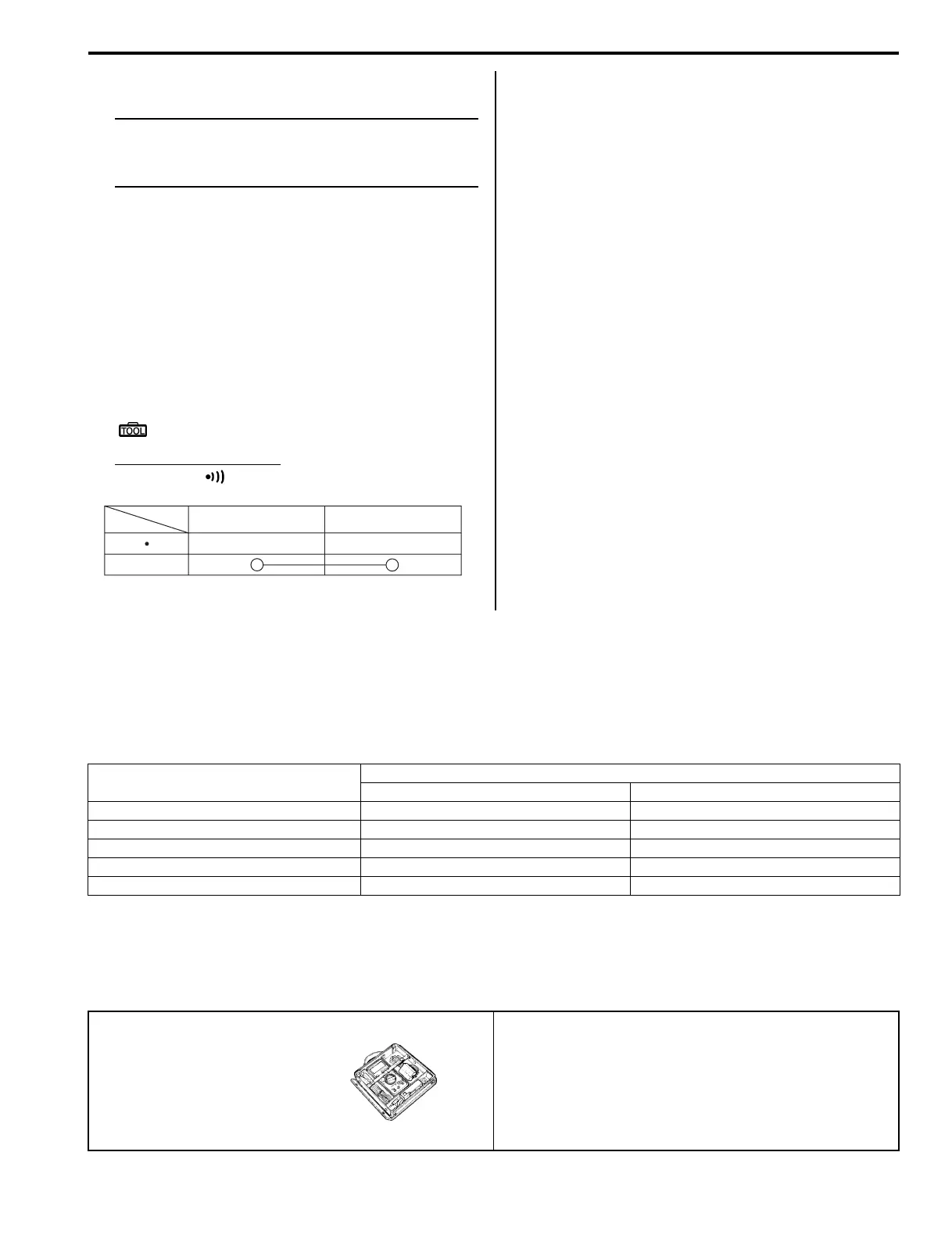
Horn Button Inspection
1) Disconnect the horn connectors as shown in the
wiring harness routing diagram. Refer to “Wiring
Harness Routing Diagram in Section 9A (Page 9A-
8)”.
2) Inspect the horn button for continuity with the tester.
If any abnormality is found, replace the horn button
with a new one.
Refer to “Handlebars Removal and Installation in
Section 6B (Page 6B-3)”.
Special tool
: 09900–25008 (Multi-circuit tester set)
Tester knob indication
Continuity ( )
3) Connect the horn connectors.
Horn Inspection
1) Disconnect the horn connectors as shown in the
wiring harness routing diagram. Refer to “Wiring
Harness Routing Diagram in Section 9A (Page 9A-
8)”.
2) Connect a 12 V battery to the terminals. If the sound
is not heard from the horn, replace the horn with a
new one.
3) Connect the horn connectors.
Horn Removal and Installation (For P-17, 24)
B827H19306015
Removal
1) Disconnect the horn connectors and remove the
horn by removing the mounting bolt.
Installation
Install the horn in the reverse order of removal.
Specifications
Service Data (LT-A400/F, LT-F400/F)
B827H19307001
Wattage
Unit: W
Special Tools and Equipment
Special Tool
B827H19308001
Color
Position
G B/W
PUSH
I831G1930024-03
Item
Specification
P 24, 28, 33 P-17
Speedometer light 1.7 ←
High beam indicator light — 3.4
Neutral indicator light 3.4 ←
Engine oil temperature indicator light 3.4 ←
Reverse indicator light 3.4 ←
09900–25008
Multi-circuit tester set
)(Page 9C-3) / )(Page 9C-
4)

 Loading...


