Propeller Shafts: 3D-7
• After reassembling the universal joint, check the joint
movement smoothly. If a large resistance is felt to
movement, tap the bearing with a plastic mallet lightly.
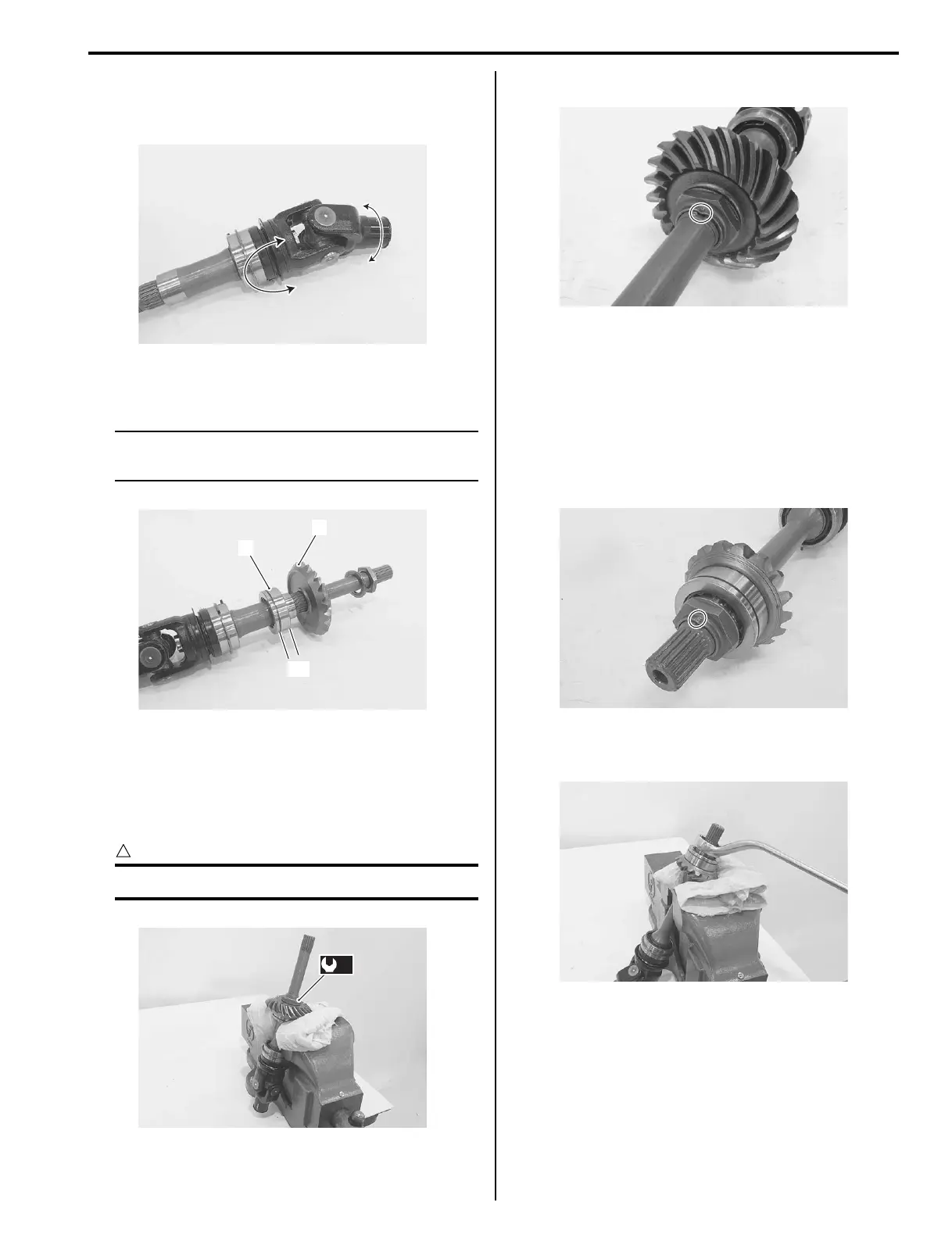
• Install the bearing (4), driven bevel gear (5), washer
and nut.
NOTE
The wider side “C” of the bearing should be
positioned bevel gear side.
• With the rear output shaft held immovable with a vise,
tighten new nut to the specified torque.
Tightening torque
Driven bevel gear nut (a): 100 N·m (10.0 kgf-m,
72.5 lb-ft)
CAUTION
!
Replace the removed nut with a new one.
• Stake the nut with a center punch.
Rear Output Shaft Disassembly and Assembly
(LT-F400/F)
B827H13406017
Refer to “Output Shaft Removal and Installation
(Page 3D-3)”.
Disassembly
1) Using a chisel, unlock the nut.
2) With the rear output shaft held immovable with a
vise, remove the nut.
I827H1340032-01
5
4
“C”
I827H1340033-02
(a)
I827H1340034-01
I827H1340035-01
I827H1340036-01
I827H1340037-01

 Loading...


