3D-8 Propeller Shafts:
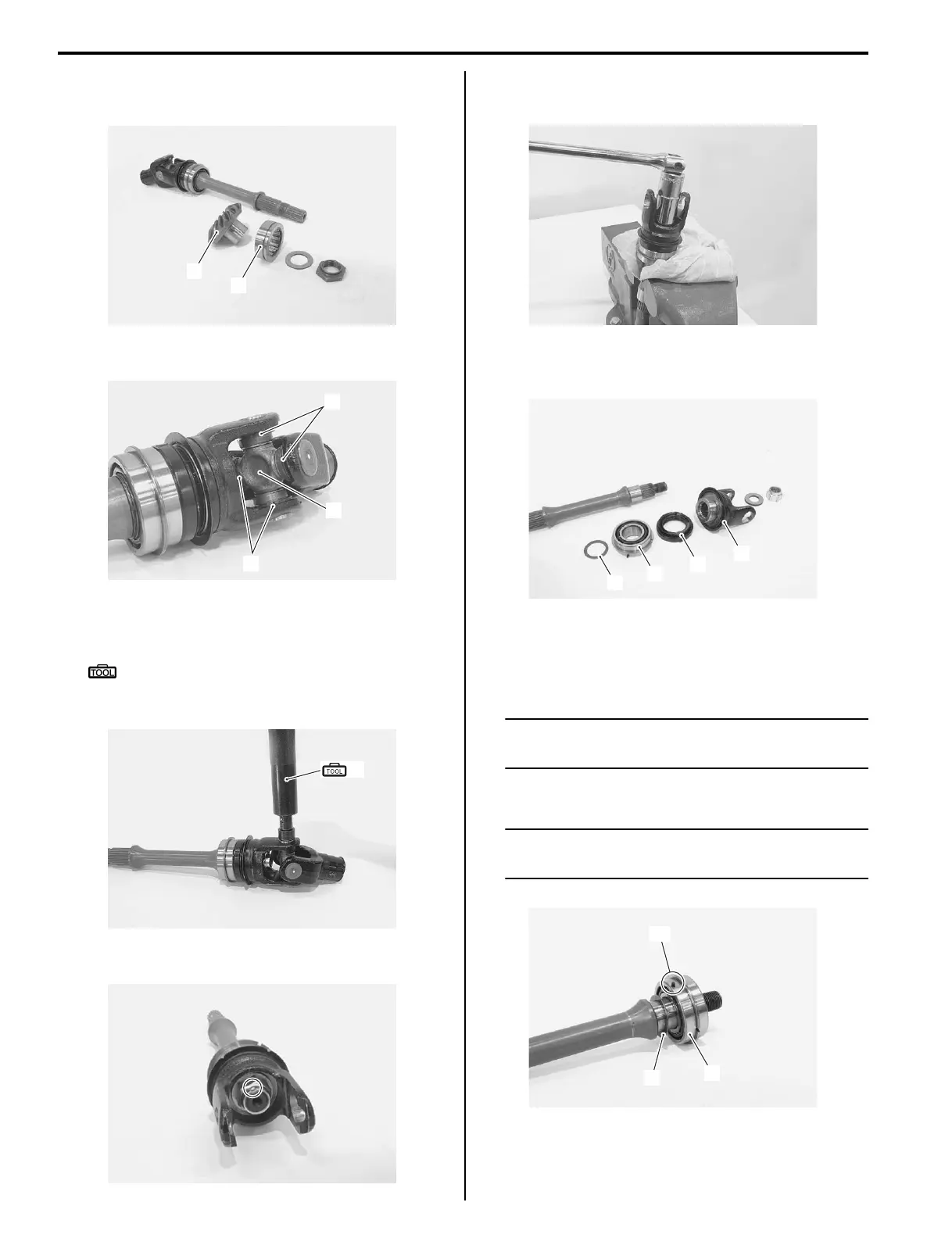
3) Remove the washer, bearing (1) and driven bevel
gear (2).
4) Remove the C-rings (3) from the universal joint (4).
5) Remove the bearings by tapping them with the
special tool and hammer.
Special tool
(A): 09913–70210 (Bearing installer set)
6) Remove the universal joint.
7) Using a chisel, unlock the nut.
8) With the rear output shaft held immovable with a
vise, remove the nut.
9) Remove the washer, joint yoke (5), oil seal (6),
bearing (7) and shim (8).
Assembly
Assemble the rear output shaft in the reverse order of
disassembly. Pay attention to the following points:
NOTE
Apply engine oil to each rotating part before
reassembling.
• Install the shim (1) and bearing (2).
NOTE
The bearing knock-pin “A” should be
positioned shim side.
1
2
I827H1340038-02
3
3
4
I827H1340039-01
(A)
I827H1340040-02
I827H1340041-02
I827H1340042-01
6
7
8
5
I827H1340043-02
1
2
“A”
I827H1340044-02

 Loading...


