3C-21 Transfer:
• Align the wide spline teeth of the arm and shaft.
• Inspect the shift rod length and adjust it if necessary.
Refer to “Shift Rod Length Adjustment (Page 3C-21)”.
Transfer Range Lever Disassembly and
Assembly
B827H13306027
Disassembly
1) Removed the transfer range lever assembly. Refer to
“Transfer Range Lever Removal and Installation
(Page 3C-20)”.
2) Disassemble the transfer range lever assembly as
shown in the transfer range lever components. Refer
to “Transfer Range Lever Components (LT-A400/F)
(Page 3C-20)” and “Transfer Range Lever
Components (LT-F400/F) (Page 3C-20)”.
Assembly
1) Assemble the transfer range lever assembly as
shown in the shift lever components. Refer to
“Transfer Range Lever Components (LT-A400/F)
(Page 3C-20)” and “Transfer Range Lever
Components (LT-F400/F) (Page 3C-20)”.
2) Install the transfer range lever assembly. Refer to
“Transfer Range Lever Removal and Installation
(Page 3C-20)”.
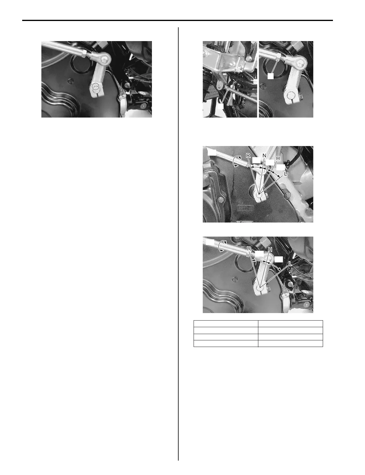
Shift Rod Length Adjustment
B827H13306028
Adjust the shift rod length along each angle of the
gearshift arm.
1) Remove the front fender. Refer to “Exterior Parts
Removal and Installation in Section 9D (Page 9D-
3)”.
2) Loosen the lock-nuts (1).
3) Turn shift rod in or out and set the gearshift arm
angle as shown in the figure.
4) Tighten the lock-nuts.
5) Install the removed parts.
Reverse Switch Inspection (LT-F400/F)
B827H13306029
Inspect the reverse switch in the following procedures:
1) Remove the left inner fender. Refer to “Exterior Parts
Removal and Installation in Section 9D (Page 9D-
3)”.
I827H11A0025-01
[A]: LT-A400/F “c”: 33°
[B]: LT-F400/F “d”: 56°
“a”: 33° “e”: 40°
“b”: 30°
1
1
I827H1330057-01
[A]
“a”
“b”
“c”
I827H1330058-01
“d”
“e”
[B]
I827H1330059-01

 Loading...


