9A-8 Wiring Systems:
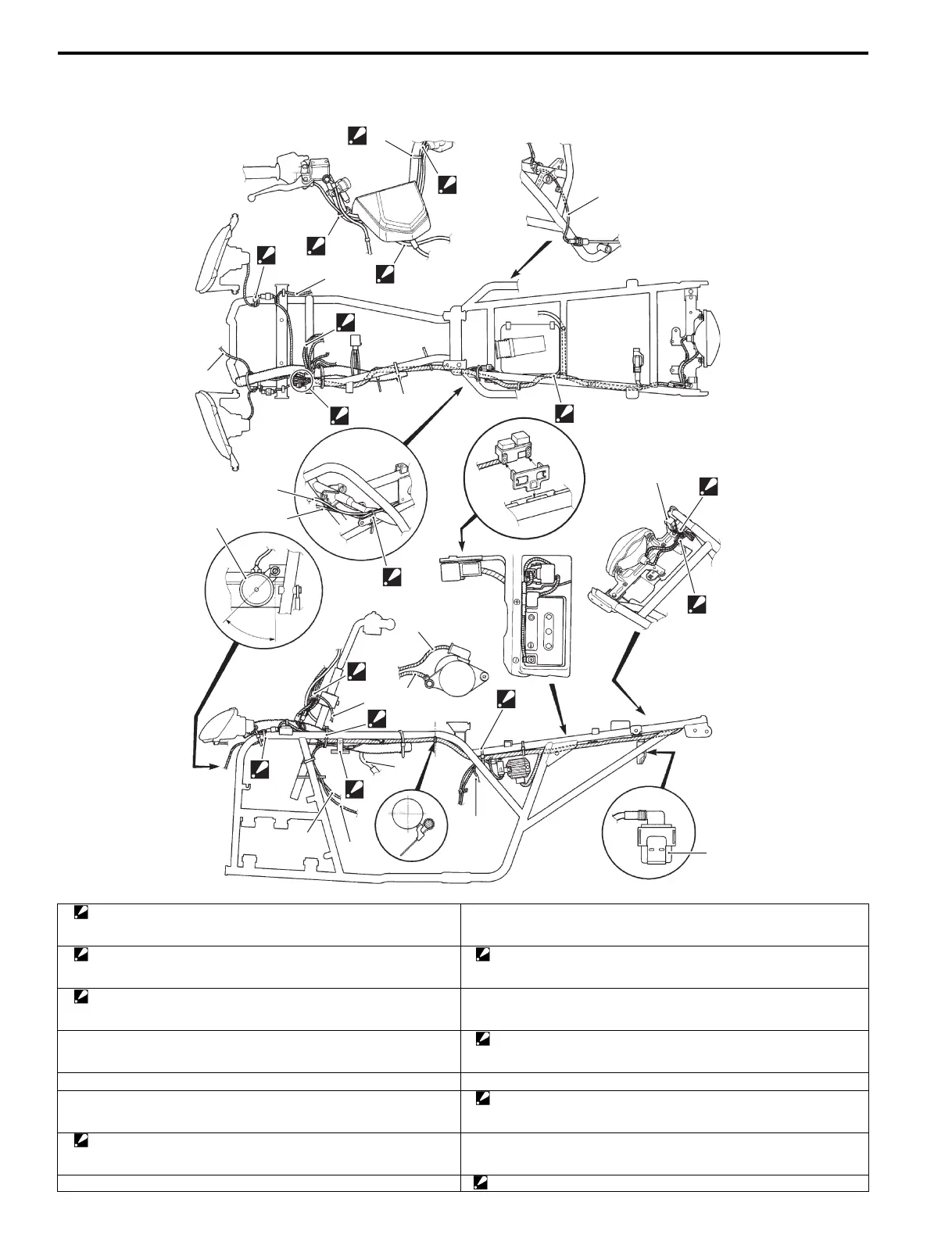
Wiring Harness Routing Diagram
B827H19102002
2
1
“A”
“B”
10
4
3
5
“D”
“C”
8
9
7
22
21
20
19
10
8
9
13
14
17
18
“G”
15
16
12
“a”
11
6
“E”
“F”
I827H1910901-06
1. Clamp
: Bind the handlebar switch lead wire, parking/rear brake light switch
lead wire and horn button lead wire (P-17, 24) with the clamp.
16. Cooling fan thermo-switch and engine oil temperature switch lead wire
2. Clamp
:Bind the front brake light switch and throttle cable with the clamp.
17. Clamp
: Bind the wiring harness, cooling fan motor lead wire and starter cable
with the clamp.
3. Clamp
: Bind the right headlight lead wire and mud protector (P-24) with the
clamp.
18. High tension cord
4. Power source terminal lead wire 19. Clamp
: Bind the wiring harness, GP switch lead wire and generator lead wire
with the clamp.
5. Horn lead wire (P-17, 24) 20. CDI unit
6. Clamp (P-28,33) 21. Clamp
:Bind the rear combination light lead wire, reversing light lead wire (P-
17) and reversing light relay lead wire (P-17) with the clamp.
7. Clamp
: Bind the Starter motor lead wire and engine ground lead wire with the
clamp.
22. Reversing light relay (P-17)
8. starter motor lead wire “A”: Pass the lead wires to front side of handlebars.

 Loading...


