Wiring Systems: 9A-9
9. Engine ground lead wire “B”: Pass the front brake light switch lead wire behind the speedometer
cable.
10. Rear brake light switch lead wire “C”: Pass the starter cable between frame and harness guide, and horn lead
wire inside of frame.
11. Horn (P-17,24) “D”: Pass the indicator light lead wire in front of other lead wires.
12. Clamp
: Bind the left headlight lead wire, horn lead wire (P-17, 24) and mud
protector (P-24) with the clamp.
“E”: Pass the wiring harness over the hook of air cleaner box.
13. Clamp
: Bind the handlebar switch lead wire, ignition switch lead wire, indicator
light lead wire, speedometer cable, reverse switch lead wire (LT-F400/
F) and horn lead wire (P-17, 24) with the clamp.
“F”: Pass the wiring harness and cooling fan motor lead wire inside the
cooling fan bracket, and starter cable outside.
14. Reverse switch lead wire (LT-F400/F) “G”: Move the tube on the rear combination light lead wire to the coupler
side before binding.
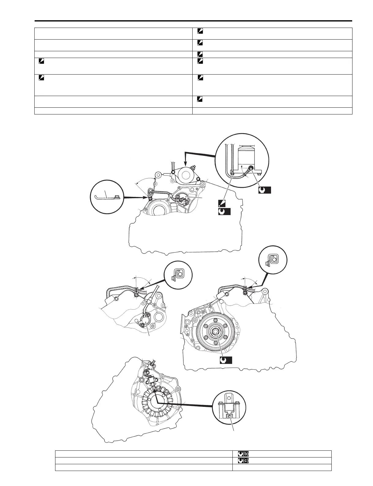
15. Cooling fan motor lead wire “a”: 45°
1
“a”
2
“A”
(a)
(b)
“c”
(c)
“c”
3
“b”
4
I827H1910902-01
1. Clamp :7.0 N⋅m (0.7 kgf-m, 5.0 lb-ft)
2. GP switch (LT-A400/F) : 140 N⋅m (14.0 kgf-m, 101.0 lb-ft)
3. GP switch (LT-F400/F) “a”: Within 60°

 Loading...


