Engine Mechanical: 1D-9
Engine Assembly Installation
B827H11406014
Reinstall the engine in the reverse order of removal. Pay
attention to the following points:
NOTE
The engine mounting nuts are self-locking.
Once the nut has been removed, it is no
longer any use. Be sure to use new nuts, and
then tighten them to the specified torque.
• Apply thread lock to the engine mounting bracket
bolts and tighten them to the specified torque.
: Thread lock cement 99000–32110
(THREAD LOCK CEMENT SUPER 1322 or
equivalent)
Tightening torque
Engine mounting bracket bolt (a): 28 N·m (2.8
kgf-m, 20.0 lb-ft)
• Install the front propeller shaft and front differential
assembly. Refer to “Front Drive (Differential)
Assembly Removal and Installation (LT-A400F, LT-
F400F) in Section 3B (Page 3B-4)”.
• Install the right footrest. Refer to “Footrest Removal
and Installation in Section 9E (Page 9E-2)”.
• Install the rear brake pedal. Refer to “Rear Brake
Pedal Removal and Installation in Section 4A
(Page 4A-12)”.
• Install the exhaust pipe and muffler. Refer to “Muffler /
Exhaust Pipe Removal and Installation in Section 1K
(Page 1K-2)”.
• Install the carburetor. Refer to “Carburetor Assembly
Removal and Installation in Section 1G (Page 1G-
17)”.
• After remounting the engine, route the wiring harness,
cables and hoses properly. Refer to “Wiring Harness
Routing Diagram in Section 9A (Page 9A-8)” and
“Throttle Cable Routing Diagram (Page 1D-1)”.
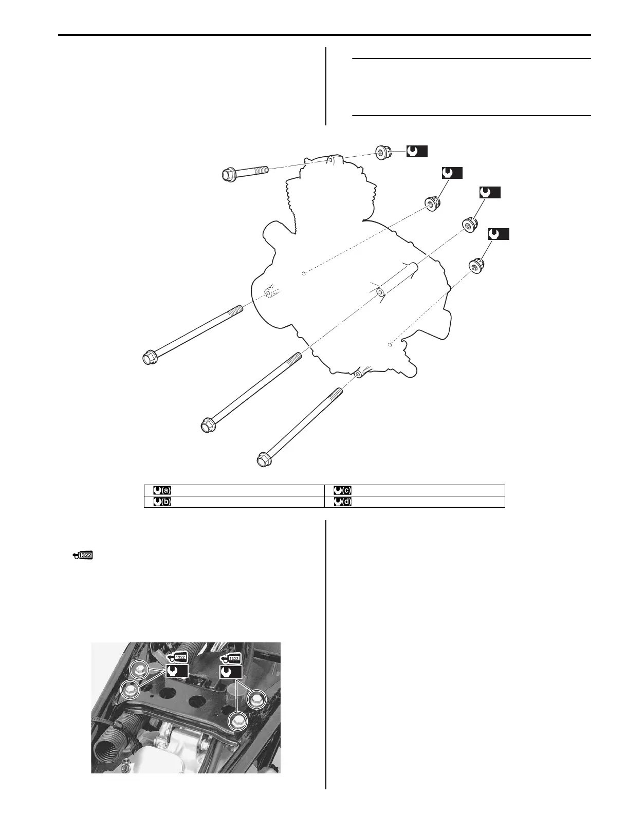
(b)
(a)
(c)
(d)
I827H1140252-01
:40 N⋅m (4.0 kgf-m, 29.0 lb-ft) : 55 N⋅m (5.5 kgf-m, 40.0 lb-ft)
:55 N⋅m (5.5 kgf-m, 40.0 lb-ft) : 55 N⋅m (5.5 kgf-m, 40.0 lb-ft)
(a)
(a)
I827H1140253-02

 Loading...


