1J-10 Charging System:
Regulator / Rectifier Inspection
B827H11A06005
Inspect the regulator/rectifier in the following procedures:
1) Turn the ignition switch OFF.
2) Remove the rear fender. Refer to “Exterior Parts Removal and Installation in Section 9D (Page 9D-3)”.
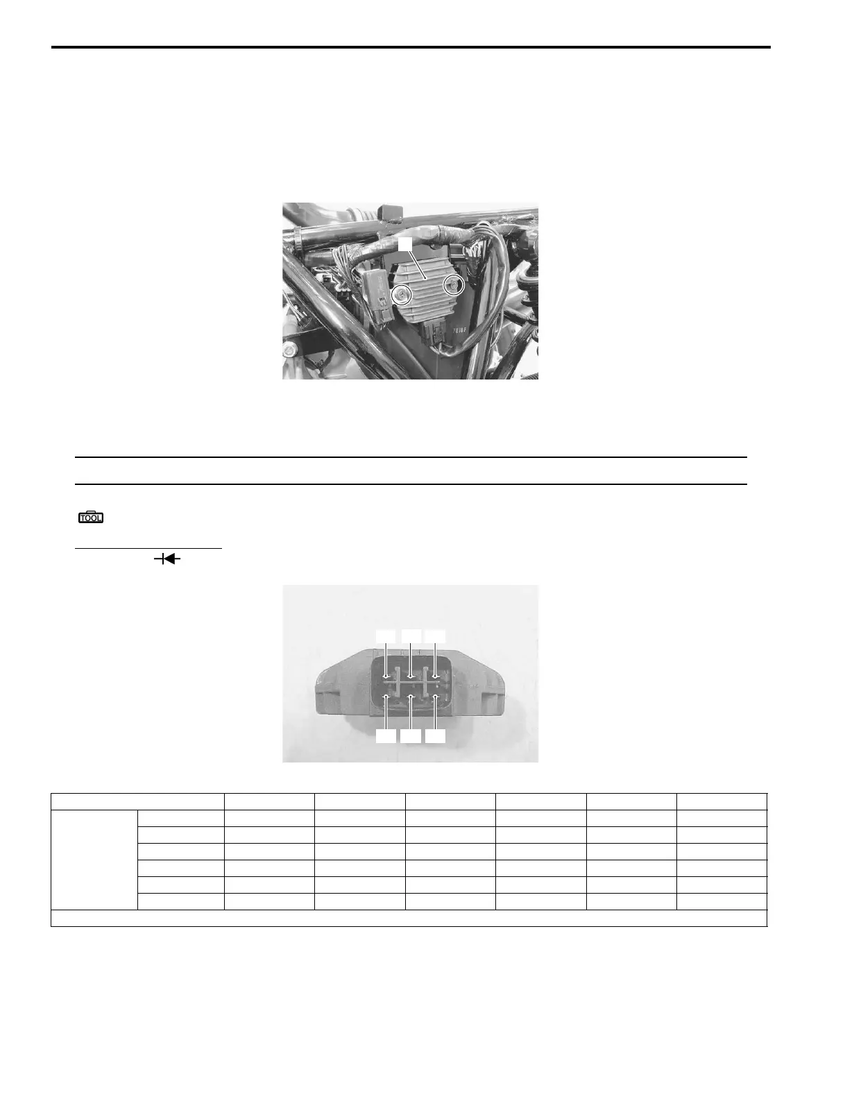
3) Disconnect the coupler and remove the regulator/rectifier (1).
4) Measure the voltage between the terminals using the multi-circuit tester as indicated in the following table. If the
voltage is not within the specified value, replace the regulator/rectifier with a new one.
NOTE
If the tester reads 1.4 V and below when the tester probes are not connected, replace its battery.
Special tool
: 09900–25008 (Multi-circuit tester set)
Tester knob indication
Diode test ( )
Unit: V
5) Connect the regulator/rectifier coupler and reinstall the removed parts.
1
I827H11A0035-01
“C”
“D” “E” “F”
“A”
“B”
I827H11A0030-01
“A” “B” “C” “D” “E” “F”
(–) probe of
tester to:
“A” — * 0.4 – 0.7 0.3 – 0.6 0.3 – 0.6 0.3 – 0.6
“B”*—****
“C” * * — * * *
“D” * * 0.3 – 0.6 — * *
“E” * * 0.3 – 0.6 * — *
“F” * * 0.3 – 0.6 * * —
*1.4 V and more (tester’s battery voltage)

 Loading...


