Propeller Shafts: 3D-3
Output Shaft Removal and Installation
B827H13406002
Removal
1) Remove the engine assembly from the frame. Refer
to “Engine Assembly Removal in Section 1D
(Page 1D-6)”.
2) Remove the engine top side. Refer to “Engine Top
Side Disassembly in Section 1D (Page 1D-10)”.
3) Separate the crankcase. Refer to “Engine Bottom
Side Disassembly in Section 1D (Page 1D-34)”.
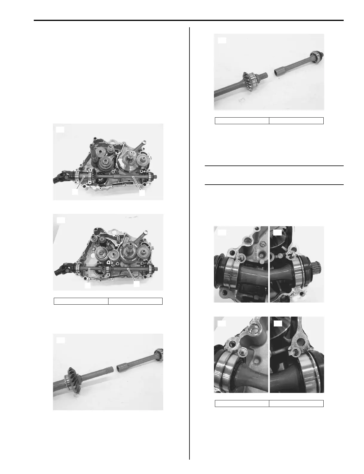
4) Remove the front output shaft (LT-A400F, LT-F400F)
(1) and rear output shaft (2).
5) Separate the front and rear output shafts. (LT-A400F,
LT-F400F)
Installation
Install the front output shaft in the reverse order of
removal. Pay attention to the following points:
NOTE
Apply engine oil to each rotating part before
reassembling.
• Align the bearing rings with their grooves in the
crankcase.
• Position the knock-pin on the bearings to the pin
grooves in the crankcase.
[A]: LT-A400F [B]: LT-F400F
1
2
[A]
I827H1340004-01
1
2
[B]
I827H1340005-01
[A]
I827H1340007-01
[A]: LT-A400F [B]: LT-F400F
[A]: LT-A400F [B]: LT-F400F
[B]
I827H1340008-01
[A] [A]
I827H1340010-02
[B] [B]
I827H1340012-02

 Loading...


