AGL7 module removal and replacement
To re place the rear-panel
connectors
Perform the fol
lowing procedure to replace the rear-panel connectors:
1. Use the Removing a module section to remove the AGL7 Genlock module
fromthemainframe. (Seepage1-10.)
2. Disconnect the cables at CH1_OUT (BLACK1 BNC), CH2_OUT (BLACK2
BNC), CH3_OUT (BLACK3 BNC), RF(R)IN (Right RF BNC), RF(L)IN
(Center RF BNC), and CW_IN (CW BNC) on the AGL7 module circuit board.
3. Use the 9/16 inch or 14 mm nut driver to remove the nut securing the damaged
connector to the chassis. Pull the connector away.
4. Perform steps 2 and 3 in reverse order to replace the connector.
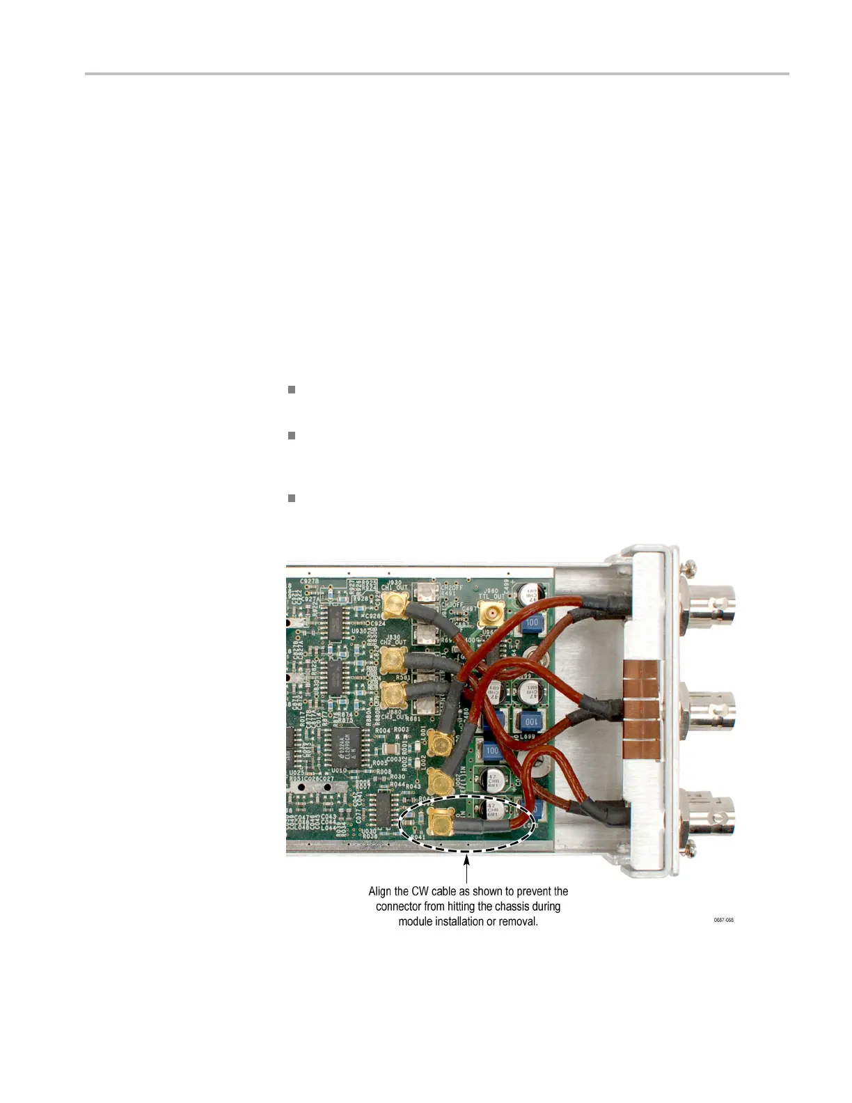
Dressing the AGL7 module BNC cables. When you are reinstalling the BNC
cables, dress the cables as follows: (See Figure 4-9.)
Dress the cables so that the t op three cables cross over the bottom three
cables at right angles.
Position the c ables to minimize bending at the exit points of the black heat
shrink. That is, make bends in the brown portion o f the coax cable between
the heat shrink tubing ends, not within the heat shrink.
Align the CW cable as shown below to prevent th
e connector from hitting the
chassis during module installation or removal.
Figure 4-9: Dressing the AGL7 module BNC cables
TG8000 Multiformat Test Signal Generator Service Manual 4–19

 Loading...


