Mainframe troubleshooting
Table 2-3: Slot diagnostics error codes (cont.)
Error
code Description Tro ub lesho oting actions
Voltage monitor tests
0x11
+5 V is out of range at the IO connector Check the fuse on the Main board and trace the voltage back to the DC-DC
converter.
0x12
+8 V is out of range at the IO connector Check the fuse on the Main board and trace the voltage back to the DC-DC
converter.
0x13
+3.3 V or the -5 VA (or both) is out of
range at the IO connector
This error code is generated when -5 V relative to +3.3V is out of range.
Measure the two voltages to determine which is out of range. Check
the fuses on the Main board and trace the voltages back to the DC-DC
converters.
IRQ test
0x14,
0x15
IRQ signal (Sx_IRQ_N) test failed This test only reads a status register in the GPS7 PLD that is tied to 0x0001.
If error c ode 0x15 occurs, it means that the read failed. The Sx_IRQ_N
signal should be tested via JTAG.
Misc.
0x99
One or more of the FPGA or PLD images
required to run the IO test process is
incorrect (out of date)
The minimum required versions are: mainframe frame FPGA (v0.14+),
GPS7 PLD (v1.7+) and GPS7 DOFPGA (v33+). The detected and
expected version numbers are printed to the console when this error code
is generated.
1
If th
e data bus or address bus tests fail (error codes 0x1 – 0x8), check that all power supplies are making it through the slot connector to the GPS7. The voltage
monitor tests are run after the data bus and address bus tests because the voltage monitor results are not meaningful if the data bus or address bus is not
working properly; so, the voltages must be manually checked if the data bus or address bus tests are failing.
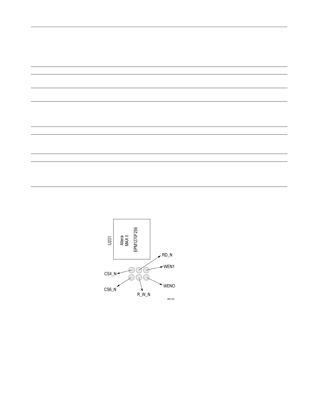
Figure 2-3: Slot diagnostics test points on the GPS7 module
TG8000 Multiformat Test Signal Generator Service Manual 2–15

 Loading...


