Home
Tektronix
Portable Generator
TG8000
Tektronix TG8000 Service Manual
4
of 1
of 1 rating
372 pages
Give review
Manual
Specs
To Next Page
To Next Page
To Previous Page
To Previous Page
Loading...
Mainframe
removal
and
installation
procedures
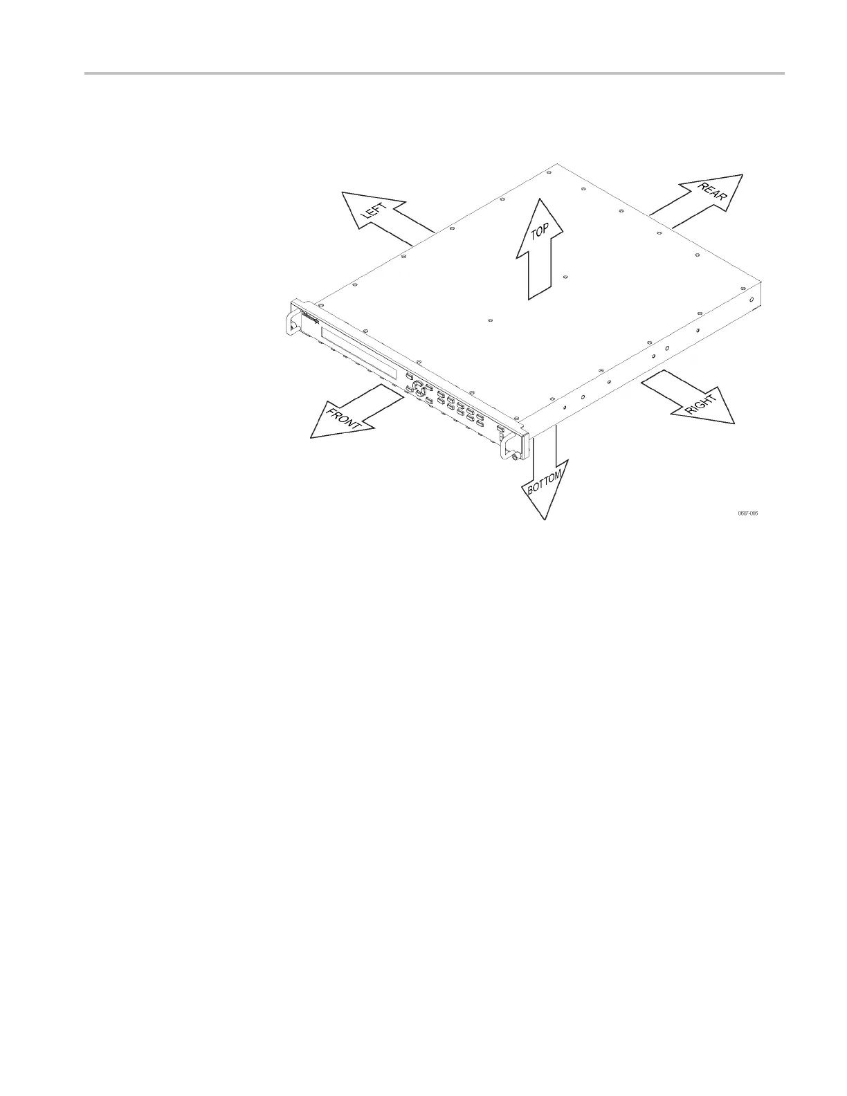
TG8000
orientation
In
this
manual,
procedures
refer
to
"front,"
"rear
,"
"top,"
etc.
of
the
TG8000.
The
following
fi
gure
shows
how
the
s
ides
are
referenced.
Figure
2-5:
TG8000
o
rientation
TG8000
Multiformat
T
est
Signal
Ge
nerator
Service
Manual
2–21
68
70
Table of Contents
Table of Contents
7
Figure 4-2: Equipment Connection for Adjusting the Output Offset and Gain
16
List of Tables
18
Default Chapter
20
Important Safety Information
20
General Safety Summary
20
Service Safety Summary
22
Terms in this Manual
23
Symbols and Terms on the Product
23
Preface
25
Manual Structure
25
Manual Conventions
26
Product Documentation
27
Table I: TG8000 Multiformat Test Signal Generator Documentation
27
Service Basics
29
Service Introduction
31
Performance Check Interval
31
Strategy for Servicing
32
Tektronix Service Offerings
32
Module Compatibility between the TG8000 and TG700 Mainframes
33
Product Maintenance
34
Service Preparation
34
Inspection and Cleaning
36
Table 1-1: External Inspection Checklist
37
Table 1-2: Internal Inspection Checklist
38
Module Installation and Removal
40
To Install a Module
41
Figure 1-1: TG8000 Slot Numbering
41
Figure 1-2: Removing the Blank Panel
42
Figure 1-3: Installing a Module
43
Figure 1-4: Securing a Module
43
To Remove a Module
44
Figure 1-5: Removing a Module
45
Repacking Instructions
46
TG8000 Mainframe
47
Mainframe Service Overview
49
Mainframe Clock Adjustment
50
Requirements for Adjustment
50
To Adjust the Master Clock Using a Frequency Signal Generator
50
Table 2-1: Equipment Required to Adjust the Master Clock Using a Signal Generator
50
Figure 2-1: Equipment Connection for Adjusting the Master Clock Frequency Using a Frequency
51
To Adjust the Master Clock Using an Installed GPS7 Module
53
Table 2-2: Equipment Required to Adjust the Master Clock Using a GPS7 Module
53
Mainframe Theory of Operation
55
Main Board
55
Power Supply Module
56
Mainframe Diagram
57
Figure 2-2: TG8000 Block Diagram
57
Mainframe Troubleshooting
58
Diagnostics and Performance Checks
58
Table 2-3: Slot Diagnostics Error Codes
61
Figure 2-3: Slot Diagnostics Test Points on the GPS7 Module
63
Table 2-4: Mainframe Troubleshooting Procedures
64
Figure 2-4: Main Board (View from Top)
66
Mainframe Removal and Installation Procedures
67
Preparation
67
Table 2-5: Tools Required for Module Removal
68
Figure 2-5: TG8000 Orientation
69
Figure 2-6: Top Cover, Line Cord, and Front Panel Assembly
70
Figure 2-7: Mainframe, Main Board, and Power Supply Module
71
Access Procedure
72
Locking Line Cord
72
Figure 2-8: Removing the Locking Line Cord
72
Top Cover
73
Figure 2-9: Removing the Top Cover
73
Front Panel Assembly
74
Figure 2-10: Removing the Front Panel Assembly
75
Front Panel Subassemblies
76
Figure 2-11: Disassembling the Front Panel Assembly
77
Power Supply Module Subassemblies
78
Figure 2-12: Installing the Fan
79
Figure 2-13: Removing the LAN Board, Fan, and RFI Filter from the Power Supply Module
80
Main Board
81
Figure 2-14: Main Board Removal
82
Mainframe Replaceable Parts List
83
Parts Ordering Information
83
Using the Replaceable Parts List
84
Table 2-6: Parts List Column Descriptions
84
Figure 2-15: Mainframe Replaceable Parts
85
Table 2-7: Mainframe Replaceable Parts
85
Table 2-8: Chassis Assembly Replaceable Parts
86
Figure 2-16: Chassis Assembly Replaceable Parts
87
Table 2-9: Front Panel Assembly Replaceable Parts
88
Figure 2-17: Front Panel Assembly Replaceable Parts
89
Table 2-10: Power Supply Assembly Replaceable Parts
90
Figure 2-18: Power Supply Assembly Replaceable Parts
91
Figure 2-19: Blank Panel Replaceable Parts
92
Table 2-11: Blank Panel Replaceable Parts
92
Table 2-12: Standard and Optional Accessories for TG8000 Mainframe
93
AG7 Audio Generator Module
95
AG7 Module Service Overview
97
AG7 Module Theory of Operation
98
Figure 3-1: Simplified Block Diagram of the AG7 Module
98
AG7 Module Interconnect Diagram
99
Figure 3-2: AG7 Module Interconnect Diagram
99
AG7 Module Troubleshooting
100
Required Equipment
100
To Back up the Instrument Settings
100
Table 3-1: Equipment Required to Troubleshoot the AG7 Module
100
AG7 Module Troubleshooting Trees
101
Figure 3-3: AG7 Module Troubleshooting Procedure (1)
101
Figure 3-4: AG7 Module Troubleshooting Procedure (2)
102
AG7 Module Removal and Replacement
103
Required Tools
103
Table 3-2: Required Tools for Removal and Replacement of AG7 Module
103
How to Replace the Rear-Panel Connectors and Chassis
104
AG7 Module Replaceable Parts List
105
Table 3-3: AG7 Module - Replaceable Parts
105
Figure 3-5: AG7 Module Exploded View
106
AGL7 Analog Genlock Module
107
AGL7 Module Service Overview
109
AGL7 Module Adjustment Procedures
110
Requirements for Adjustment
110
Required Equipment
110
Table 4-1: Equipment Required for AGL7 Module Adjustment Procedures
110
To Adjust the Output Offset and Gain
111
Figure 4-1: AGL7 Module Circuit Board
111
To Adjust the Clock Timing (Older Versions Only)
115
Figure 4-3: AGL7 Module Circuit Board (Older Versions Only)
115
Figure 4-4: Timing Relationship between CH1 and CH2 Signals
118
AGL7 Module Theory of Operation
120
Analog Genlock
120
Black Burst Generator
120
Figure 4-5: Simplified Block Diagram of the AGL7 Module
121
AGL7 Module Interconnect Diagram
122
Figure 4-6: AGL7 Module Interconnect Diagram
122
AGL7 Module Troubleshooting
123
Required Equipment
123
To Back up the Instrument Settings
123
Table 4-2: Equipment Required for AGL7 Module Troubleshooting
123
AGL7 Module Troubleshooting Trees
124
Figure 4-7: AGL7 Module Troubleshooting Procedure (1)
124
Figure 4-8: AGL7 Module Troubleshooting Procedure (2)
125
AGL7 Module Removal and Replacement
126
Required Tools
126
How to Replace the Rear-Panel Connectors and Chassis
126
Table 4-3: Required Tools for Removal and Replacement of AGL7 Module
126
Figure 4-9: Dressing the AGL7 Module BNC Cables
127
AGL7 Module Replaceable Parts List
129
Table 4-4: AGL7 Module - Replaceable Parts
129
ATG7 Analog Test Generator Module
131
ATG7 Module Service Overview
133
ATG7 Module Adjustment Procedures
134
Requirements for Adjustment
134
Required Equipment
134
Table 5-1: Equipment Required for ATG7 Module Adjustment Procedures
134
To Adjust the Output Offset and Gain
135
To Adjust Chroma Gain
138
ATG7 Module Theory of Operation
141
ATG7 Module Interconnect Diagram
142
ATG7 Module Troubleshooting
143
Required Equipment
143
To Back up the Instrument Settings
143
Table 5-2: Equipment Required for ATG7 Module Troubleshooting
143
ATG7 Module Troubleshooting Trees
144
ATG7 Module Removal and Replacement
146
Required Tools
146
How to Replace the Rear-Panel Connectors and Chassis
146
Table 5-3: Required Tools for Removal and Replacement of ATG7 Module
146
ATG7 Module Replaceable Parts List
148
Table 5-4: ATG7 Module - Replaceable Parts
148
AVG7 Analog Video Generator Module
151
AVG7 Module Service Overview
153
AVG7 Module Adjustment Procedures
154
Requirements for Adjustment
154
Required Equipment
155
Table 6-1: Equipment Required for the AVG7 Module Adjustment Procedures
155
To Adjust the Output Offset and Gain
156
To Adjust Group Delay
158
To Adjust the Frequency Response
162
To Adjust Interchannel Delay
166
To Confirm the Frequency Response
170
To Confirm the Interchannel Delay
170
AVG7 Module Theory of Operation
171
AVG7 Module Interconnect Diagram
173
AVG7 Module Troubleshooting
174
Required Equipment
174
To Back up the Instrument Settings
174
Table 6-2: Equipment Required for AVG7 Module Troubleshooting
174
AVG7 Module Troubleshooting Trees
175
AVG7 Module Removal and Replacement
177
Required Tools
177
Table 6-3: Required Tools for Removal and Replacement of the AVG7 Module
177
How to Replace the Rear-Panel Connectors and Chassis
178
AVG7 Module Replaceable Parts List
179
Table 6-4: AVG7 Module - Replaceable Parts
179
AWVG7 Analog Wideband Video Generator Module
181
AWVG7 Module Service Overview
183
AWVG7 Module Adjustment Procedures
184
Requirements for Adjustment
184
Required Equipment
185
Table 7-1: Equipment Required for AWVG7 Module Adjustment Procedures
185
To Adjust the Output Offset and Gain
186
To Adjust the Frequency Response
189
AWVG7 Module Theory of Operation
193
AWVG7 Module Interconnect Diagram
195
AWVG7 Module Troubleshooting
196
Required Equipment
196
To Back up the Instrument Settings
196
Table 7-2: Equipment Required for AWVG7 Module Troubleshooting
196
AWVG7 Module Troubleshooting Trees
197
AWVG7 Module Removal and Replacement
199
Required Tools
199
Table 7-3: Required Tools for Removal and Replacement of AWVG7 Module
199
How to Replace the Rear-Panel Connectors and Chassis
200
AWVG7 Module Replaceable Parts List
201
Table 7-4: AWVG7 Module - Replaceable Parts
201
BG7 Black Generator Module
203
BG7 Module Service Overview
205
BG7 Module Adjustment Procedures
206
Requirements for Adjustment
206
Required Equipment
206
Table 8-1: Equipment Required for BG7 Module Adjustment Procedures
206
To Adjust the Output Offset and Gain
207
To Adjust Chroma Gain (Option CB Only)
209
BG7 Module Theory of Operation
212
BG7 Module Interconnect Diagram
213
BG7 Module Troubleshooting
214
Required Equipment
214
To Back up the Instrument Settings
214
Table 8-2: Equipment Required for BG7 Module Troubleshooting
214
BG7 Module Troubleshooting Trees
215
BG7 Module Removal and Replacement
217
Required Tools
217
Table 8-3: Required Tools for Removal and Replacement of BG7 Module
217
How to Replace the Rear-Panel Connectors and Chassis
218
BG7 Module Replaceable Parts List
219
Table 8-4: BG7 Module - Replaceable Parts
219
DVG7 Digital Video Generator Module
221
DVG7 Module Service Overview
223
DVG7 Module Adjustment Procedures
224
Requirements for Adjustment
224
Required Equipment
224
To Adjust the Output Level
225
DVG7 Module Theory of Operation
232
DVG7 Module Interconnect Diagram
234
DVG7 Module Troubleshooting
235
Required Equipment
235
To Back up the Instrument Settings
235
DVG7 Module Troubleshooting Trees
236
DVG7 Module Removal and Replacement
238
Required Tools
238
How to Replace the Rear-Panel Connectors and Chassis
239
DVG7 Module Replaceable Parts List
240
GPS7 GPS Synchronization and Timecode Module
243
GPS7 Module Service Overview
245
GPS7 Module Adjustment Procedures
246
Requirements for Adjustment
246
Required Equipment
246
To Adjust Black Burst Level and Offset
247
GPS7 Module Theory of Operation
249
GPS7 Module Troubleshooting
252
Required Equipment
252
Problem Identification
253
Troubleshooting Procedures
255
GPS7 Module Removal and Replacement
267
Required Tools
267
To Remove the GPS7 Module
268
To Replace the Antenna Power Indicator (Light Pipe)
268
How to Replace the Rear-Panel Connectors and Chassis
268
GPS7 Module Replaceable Parts List
270
HD3G7 HD 3 Gb/S SDI Video Generator Module
273
HD3G7 Module Service Overview
275
HD3G7 Module Adjustment Procedures
276
Required Equipment
276
Adjustment Procedures
277
HD3G7 Module Theory of Operation
283
Overview
283
FPGA and Associated Circuits
283
Clocks and Frames
284
Input and Output Boards
284
Power Supplies
285
HD3G7 Module Troubleshooting
286
Required Equipment
286
Problem Identification
287
HD3G7 Module Troubleshooting Procedures
288
HD3G7 Module Removal and Replacement
296
Required Tools
296
To Remove the HD3G7 Module
296
To Disassemble the HD3G7 Module
296
To Reassemble the HD3G7 Module
297
HD3G7 Module Replaceable Parts List
299
HDLG7 HD Dual Link Video Generator Module
303
HDLG7 Module Service Overview
305
HDLG7 Module Theory of Operation
306
HDLG7 Module Interconnect Diagram
308
HDLG7 Module Troubleshooting
309
Required Equipment
309
To Back up the Instrument Settings
309
HDLG7 Module Troubleshooting Trees
310
HDLG7 Module Removal and Replacement
312
Required Tools
312
How to Replace the Rear-Panel Connectors and Chassis
313
HDLG7 Module Replaceable Parts List
314
HDVG7 HDTV Digital Video Generator Module
317
HDVG7 Module Service Overview
319
HDVG7 Module Adjustment Procedures
320
Requirements for Adjustment
320
Required Equipment
320
To Adjust the Output Level
321
HDVG7 Module Theory of Operation
328
HDVG7 Module Interconnect Diagram
330
HDVG7 Module Troubleshooting
331
Required Equipment
331
To Back up the Instrument Settings
331
HDVG7 Module Troubleshooting Trees
332
HDVG7 Module Removal and Replacement
334
Required Tools
334
How to Replace the Rear-Panel Connectors and Chassis
335
HDVG7 Module Replaceable Parts List
336
SDI7 Dual Channel SD/HD/3G SDI Video Generator Module
339
SDI7 Module Service Overview
341
SDI7 Module Adjustment Procedures
342
Requirements for Adjustment
342
Required Equipment
342
Adjustment Procedures
343
SDI7 Module Theory of Operation
350
Overview
350
FPGA and Associated Circuits
350
Clocks and Frames
351
Output Boards
351
Power Supplies
352
SDI7 Module Troubleshooting
353
Required Equipment
353
Problem Identification
354
Troubleshooting Procedures
355
SDI7 Module Removal and Replacement
367
Required Tools
367
To Remove the SDI7 Module
367
To Disassemble the SDI7 Module
367
To Reassemble the SDI7 Module
368
Other manuals for Tektronix TG8000
User Manual
498 pages
Programmer's Manual
200 pages
Technical Reference
41 pages
Manual
12 pages
Declassification And Security Instructions
20 pages
4
Based on 1 rating
Ask a question
Give review
Questions and Answers:
Need help?
Do you have a question about the Tektronix TG8000 and is the answer not in the manual?
Ask a question
Tektronix TG8000 Specifications
General
Brand
Tektronix
Model
TG8000
Category
Portable Generator
Language
English
Related product manuals
Tektronix AFG3000 Series
86 pages
Tektronix AFG310
22 pages
Tektronix CFG253
26 pages
Tektronix AFG3021
164 pages
Tektronix AFG3252
113 pages
Tektronix AFG3102
164 pages
Tektronix AWG5204
11 pages
Tektronix AWG5200 Series
11 pages
Tektronix FG 5010
306 pages
Tektronix AWG7082C
174 pages
Tektronix AWG7000B Series
174 pages

 Loading...


