HD3G7 module removal and replacement
To reassemble
the HD3G7 module
Reassembly is more complex than disassembly, and must be done i n a specific
order to prevent damage to the HD3G7 module. These procedures will start as if
the instrume
nt has be en completely disassembled. You may start at an appropriate
step and proceed to the end.
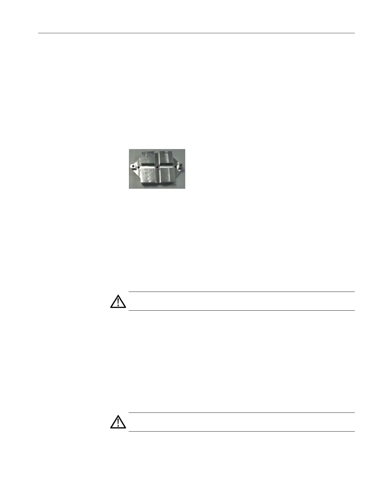
To install a new h eat sink
Follow this procedure to install a new heat sink. You will need a new gap pad as
well as the heat sink.
1. Place t he heat sink on the work surface as shown, with the bosses up.
2. Peel the protective film off of one side of the gap pad, and adhere the gap
pad to the top of the heat sink.
3. Peel the protective film off of the top side of t he gap pad.
4. Position the HD3G7 Main circuit board over the heat sink and gap pad,
aligning the holes in the circuit board (on each side of the FPGA) with the
threaded bosses of the heat sink. Press the circuit board down slightly to
adhere the gap pad to the circuit board.
5. Loosely install two of the T10 TORX s crews through the circuit board and
into the heat sink.
CAUTION. To prevent damage to the FPGA, do not tighten these screws at this
time.
To replace the circuit board
into the chassis
Follow this procedure to reinstall the circuit board assembly into the chassis.
1. Install the SDI Input circuit board (878-0199-xx) into J910 of the Main circuit
board, and install the SDI Output
circuit board (878-0200-xx) into J922 of
the Main circuit board.
2. Slide the circuit board assembly onto the chassis, guiding the BNC connectors
through the holes in the rear panel.
3. Loosely install the s ix T10 TORX screws that attach the Main circuit board to
the chassis.
CAUTION. To prevent damage to the circuit boards and to the FPGA, do not
tighten these screws at this time.
TG8000 Multiformat Test Signal Generator Service Manual 11–23

 Loading...


